An introduction to some of the typical sound level meters
1. Integral sound level meter
For non-stationary noise, it is required to measure the equivalent continuous sound level of noise Leq, defined as: in the sound field at a certain point position, with a certain period of time energy averaging method, the intermittent changes in several different A sound level, to an A sound level represents the size of the noise at that time.
The integrating sound level meter can directly display the equivalent continuous sound level of the measured noise in a certain measuring time in digital form. The performance should meet the requirements of IEC804 and GB/T17181 standards. The schematic diagram is shown in Fig. 2, which is mainly composed of microphone, preamplifier, frequency weighing amplifier, range conversion, overload indication circuit, logarithmic detector and DC amplifier, A/D converter, microprocessor, memory, LCD display, key input panel, reference calibration signal and power supply, interface circuit and other parts.
Integral Sound Level Meter Schematic Diagram
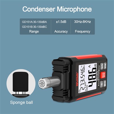
Microphone: electret test condenser microphone, convert the sound signal into electrical signal, with good stability, wide frequency response and so on.
Preamplifier: with high input impedance and low output impedance, it plays the role of impedance conversion.
Frequency counting amplification, range conversion, overload indication circuit: this part of the circuit is from the preamplifier to amplify the weak signal to reach a certain amplitude, range conversion circuit under the control of the microprocessor, to ensure that the entire amplifier in the measurement range can be undistorted to reflect the size of the input signal changes. When the signal exceeds the measurement range of the current range overload indicator circuit automatically controls the overload lamp to indicate the
Logarithmic detector and DC amplifier: It is to detect the RMS value of the AC signal from the AC amplifier which corresponds to the measured sound level and amplify it in a certain proportion, so that the DC amplifier outputs a linearly changing DC voltage corresponding to the measured sound level.
A/D converter, microprocessor, memory, interface circuit: these parts form a complete microcontroller system, the microprocessor under the control of the programme memory, the A/D converter for timed sampling, and automatic measurement, while the measurement results are stored in the memory and output to the printer or microcomputer through the interface circuit.
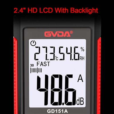
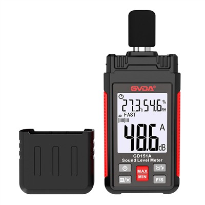
Display part and panel part: LCD display can display and output the clock, working mode, measurement data, frequency and other measurement markers and measurement results, the panel part provides a manual control interface, according to the measurement requirements, the working mode, control signals are input to the microprocessor to achieve the noise measurement and analysis.
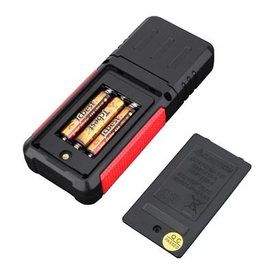
Reference calibration signal and power supply: powered by the battery (or external input) a single positive voltage is converted into the required positive and negative voltage, responsible for the power supply of the whole machine. And generate a reference signal as internal circuit calibration.