How does a multimeter detect whether the encoder is good or bad?
(1) Before using the multimeter, "mechanical zero adjustment" should be performed first, that is, when there is no electricity being measured, the pointer of the multimeter points to the position of zero voltage or zero current.
(2) When using the multimeter, do not touch the metal part of the test lead with your hands. This can ensure accurate measurement on the one hand, and personal safety on the other hand.
(3) When measuring a certain amount of electricity, you cannot change gears while measuring, especially when measuring high voltage or large current, you should pay more attention. Otherwise, the multimeter will be damaged. If you need to change gears, you should disconnect the test leads first, and then measure after changing gears.
(4) When using the multimeter, it must be placed horizontally to avoid errors. At the same time, attention should also be paid to avoiding the influence of external magnetic fields on the multimeter.
(5) After using the multimeter, the transfer switch should be placed in the maximum AC voltage range. If it is not used for a long time, the battery inside the multimeter should also be taken out to prevent the battery from corroding other components in the meter.
How to use a multimeter to check whether the encoder is good or bad
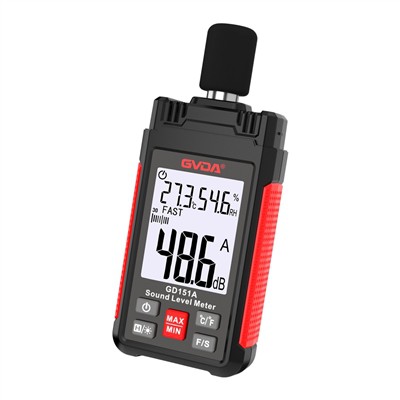
There is a 24V HTL incremental rotary encoder. Connect its six wires of 24V, 0V, A, A-, B, B- to the X23 port of CU310. It cannot work normally after powering on. The multimeter measured the voltage of the power terminal to be 2.0 V. , dismantled it and measured it again and found that the output voltage of CU310 is 24V. Suspecting that the encoder is faulty, I connected the encoder 4 to only 24V. The measured voltage to 0 is A=0V, A-=24V, B=24V, B-=0V. Is the encoder normal? The encoder manufacturer said that the normal value should be around 15V? This is true for several of the same encoders.
A multimeter cannot accurately check whether the encoder is completely normal. A multimeter can simply detect whether the incremental encoder is good or bad:
Power on the incremental encoder and measure the output voltage of A/B/Z. If there is no output voltage, the power supply part is damaged or the main chip is damaged. If there is a certain phase, slowly rotate the encoder shaft. The A/B phase should be the alternating voltage. From high level to low voltage, the probability is 1/2, and Z is a high level once in a circle. The high level voltage is generally 2V lower than the input voltage or higher. If a certain phase never appears high level, Or the output level is very low, then the phase is damaged.
If this method of detection is good, then look at the oscilloscope to see whether the waveform has been distorted and whether there are missing pulses, and then check again.