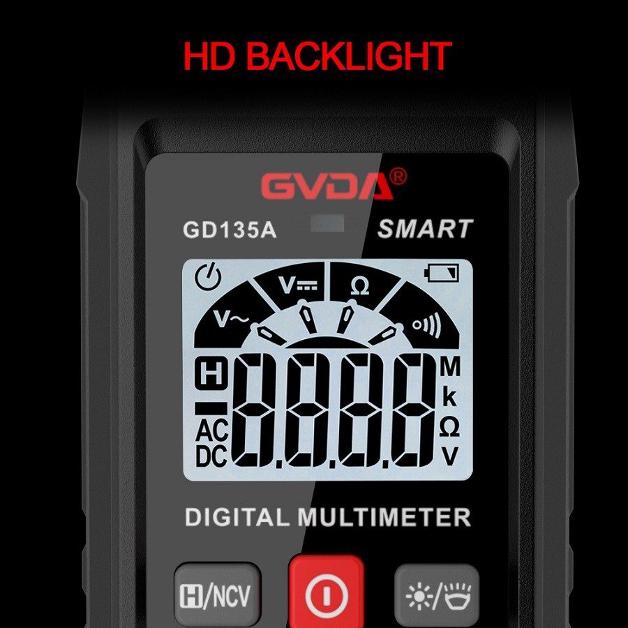
Operating Instructions and Seven Precautions for Multimeters
(1) Familiarize oneself with the meanings of the symbols on the dial and the main functions of the knobs and selector switches.
(2) Perform mechanical zeroing.
(3) Select the gear and range of the conversion switch based on the type and size being measured, and find the corresponding scale line.
(4) Select the position of the probe socket.
(5) Measuring voltage: When measuring voltage (or current), it is important to choose the appropriate range. If a small range is used to measure high voltage, there is a risk of burning the meter; If a large range is used to measure small voltages, the pointer deflection will be too small to read. The selection of measuring range should try to deflect the pointer to about 2/3 of the full scale. If the size of the measured voltage is not clear beforehand, the highest range gear should be selected first, and then gradually reduced to the appropriate range.
Measurement of AC voltage: Place one switch of the multimeter in the AC/DC voltage range, and the other switch in the appropriate range of AC voltage. Connect the two probes of the multimeter in parallel with the tested circuit or load.
Measurement of DC voltage: Place one switch of the multimeter in the AC/DC voltage range, and the other switch in the appropriate range of DC voltage. Connect the "+" probe (red probe) to the high potential and the "-" probe (black probe) to the low potential, allowing current to flow in from the "+" probe and out from the "-" probe. If the probe is connected in the opposite direction, the pointer of the meter head will deflect in the opposite direction, making it easy to bend the pointer.
(6) Current measurement: When measuring DC current, place one switch of the multimeter in the DC current range and the other switch in the appropriate range of 50uA to 500mA. The selection and reading method of the current range is the same as that of voltage. When measuring, the circuit must be disconnected first, and then the multimeter should be connected in series to the tested circuit in the direction of the current from "+" to "-", that is, the current flows in from the red probe and out from the black probe. If the multimeter is mistakenly connected in parallel with the load, it may cause a short circuit and burn out the instrument due to the low internal resistance of the meter head. The reading method is as follows: actual value=indicated value x range/full offset
(7) Resistance measurement: When measuring resistance with a multimeter, the following methods should be followed:
Mechanical zeroing. Before use, the pointer positioning screw should be adjusted to zero the current reading to avoid unnecessary errors.
Choose the appropriate magnification gear. The scale line of the multimeter's ohm range is uneven, so the selection of the magnification range should keep the pointer in the thinner part of the scale line, and the closer the pointer is to the middle of the scale, the more accurate the reading. In general, the pointer should be placed between 1/3 and 2/3 of the scale.
C ohm zeroing. Before measuring resistance, short circuit the two probes and adjust the "Ohm (Electrical) Zero Knob" so that the pointer is just pointing to the zero position on the right side of the Ohm scale line. If the pointer cannot be adjusted to zero, it indicates that the battery voltage is insufficient or there is an internal problem with the instrument. And every time the magnification gear is changed, it is necessary to perform Ohmic zeroing again to ensure accurate measurement.
D reading: Multiply the reading on the meter by the multiplier to obtain the resistance value of the measured resistor.