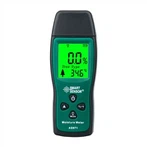
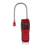
1. Clamp meters come in a wide variety of shapes and sizes.
The design of jaw size makes the calibration process difficult, and corresponding calibration equipment needs to be selected.
2. Most clamp meters today are multifunctional.
In addition to current, most clamp meters can generally measure voltage, continuity, and other functions common to digital,
3. Not all calibrators are up to the job.
At higher outputs, many calibrators limit the continuous output of large currents. Also, you must use a calibrator that is accurate enough and that the compliance voltage is sufficient to drive the coil. Fluke uses "L-COMP" (Inductive Compensation) technology to increase the compliance voltage to drive the load.
Coil inductance can cause failure, so avoid current sources that are not designed for current coils. Transients when turning current on and off can cause the current source to trip.
4. Current coil winding (number of turns) and range are very important.
The number of turns of the coil used must be sufficient to test the entire current range of the current clamp. The coil winding determines the amount of current. For example, a calibrator with 50 turns outputting 20 A will present up to 1,000 A on the clamp meter.
5. Don't ignore attachments.
Some clamp meters may have flexible current probes, such as the Fluke iFlex, which must be calibrated with the clamp meter.
6. High current will generate heat.
The design of the current coil must be able to dissipate as much heat as possible. Coils generally have a maximum operating time specification at higher currents.
7. Positioning is very important.
When aligning the clamp meter with the current coil, pay attention to the current clamp stray field and position sensitivity. Avoid interference fields from other equipment and current conductors. Note the clamp meter alignment marks. Align the clamp meter's axis parallel to the coil axis and align the jaw plane perpendicular to the coil wire.


