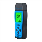
Analyze the function and principle of multimeter
Multimeters, also known as multimeters, multimeters, three-meters, multimeters, etc., are indispensable measuring instruments in power electronics and other departments. Generally, the main purpose is to measure voltage, current and resistance. Multimeters are divided into pointer multimeters and digital multimeters according to the display method. It is a multi-functional and multi-range measuring instrument. Generally, the multimeter can measure DC current, DC voltage, AC current, AC voltage, resistance and audio level, etc., and some can also measure AC current, capacitance, inductance and semiconductor. Some parameters (such as β) and so on.
A multimeter is a magnetoelectric instrument with a rectifier that can measure various electrical parameters such as AC and DC current, voltage and resistance. For each electrical quantity, there are generally several ranges. Also known as multimeter or multimeter for short. The multimeter is composed of a magnetoelectric ammeter (meter head), a measuring circuit and a selection switch. Various electrical parameters can be measured conveniently by changing the selection switch. The main basis of its circuit calculation is the closed circuit Ohm's law. There are many types of multimeters, and they should be selected according to different requirements when using them.
Basic functions
The multimeter can be used not only to measure the resistance of the measured object, but also to measure the DC voltage. Some multimeters can even measure the main parameters of transistors and the capacitance of capacitors. It is one of the basic skills of electronic technology to be fully proficient in the use of multimeters. Common multimeters include pointer multimeters and digital multimeters. The pointer multimeter is a multi-functional measuring instrument with the meter head as the core component, and the measured value is read by the pointer of the meter head. The measured value of the digital multimeter is directly displayed in digital form by the liquid crystal display, which is easy to read, and some also have a voice prompt function. A multimeter is a meter that combines a voltmeter, an ammeter and an ohmmeter in one head.
The DC current range of the multimeter is a multi-range DC voltmeter. The voltage range can be expanded by connecting the closed-circuit voltage dividing resistor in parallel with the meter head. The DC voltage file of the multimeter is a multi-range DC voltmeter. Connecting the voltage dividing resistor in series with the meter head can expand its voltage range. Different voltage dividing resistors have different corresponding measuring ranges. The head of the multimeter is a magnetoelectric system measuring mechanism, which can only pass through direct current, and use diodes to change alternating current into direct current, thereby realizing the measurement of alternating current.
Structure and composition
The multimeter is composed of three main parts: meter head, measuring circuit and changeover switch. The multimeter is a basic tool in the field of electronic testing, and it is also a widely used testing instrument. Multimeters are also called multimeters, three-purpose meters (A, V, Ω are current, voltage, and resistance), multiplexers, and meters. Multimeters are divided into pointer multimeters and digital multimeters. There is also a display with oscilloscope function. Wave multimeter is a multi-functional, multi-range measuring instrument. General multimeters can measure DC current, DC voltage, AC voltage, resistance and audio level, etc., and some can also measure AC current, capacitance, inductance, temperature and some parameters of semiconductors (diodes, transistors). Digital multimeters have become mainstream and have replaced analog meters. Compared with analog instruments, digital instruments have high sensitivity, high precision, clear display, strong overload capacity, easy to carry, and more convenient and simple to use.
header
The head of the multimeter is a sensitive galvanometer. The dial on the head is printed with various symbols, scale marks and values. The symbol A-V-Ω indicates that the ammeter is a multimeter that can measure current, voltage and resistance. There are multiple scale lines printed on the dial, among which the one marked with "Ω" on the right is the resistance scale line, the right end is zero, the left end is ∞, and the scale value distribution is uneven. The symbol "-" or "DC" means direct current, "~" or "AC" means alternating current, and "~" means the scale line common to both AC and DC. Several rows of numbers under the scale line are the scale values corresponding to the different positions of the selector switch.
There is also a mechanical zero position adjustment knob on the meter head to correct the zero position of the pointer at the left end.
switch
The selection switch of the multimeter is a multi-position rotary switch. Used to select measurement items and ranges.
General multimeter measurement items include: "mA"; DC current, "V(-)": DC voltage, "V(~)": AC voltage, "Ω": resistance. Each measurement item is divided into several different ranges for selection.
Test lead and test lead jack
The test leads are divided into red and black. When using, insert the red test lead into the jack marked "+", and insert the black test lead into the jack marked "-".
Meter (pointer type)
It is a high-sensitivity magnetoelectric DC ammeter. The main performance indicators of the multimeter basically depend on the performance of the meter head. The sensitivity of the meter head refers to the DC current value flowing through the meter head when the pointer of the meter head is deflected at full scale. The smaller the value, the higher the sensitivity of the meter head. The greater the internal resistance when measuring voltage, the better its performance. There are four scale lines on the meter head, and their functions are as follows: the bars (from top to bottom) are marked with R or Ω, indicating the resistance value, and when the switch is in the ohm block, read this scale line. The second bar is marked with ∽ and VA, indicating the AC, DC voltage and DC current value. When the transfer switch is in the AC, DC voltage or DC current gear, and the range is in a position other than AC 10V, read this scale Wire. The third line is marked with 10V, which indicates the AC voltage value of 10V. When the switch is in the AC and DC voltage range and the range is at AC 10V, read this scale line. The fourth bar, labeled dB, indicates the audio level.
Meter (digital)
The head of a digital multimeter is generally composed of an A/D (analog/digital) conversion chip + peripheral components + liquid crystal display. The accuracy of the multimeter is affected by the head. The number converted by the A/D chip is generally also called For 3 1/2 digit multimeter, 4 1/2 digit multimeter and so on. Commonly used chips are ICL7106 (3.5-digit LCD manual range classic chip, subsequent versions are 7106A, 7106B, 7206, 7240, etc.), ICL7129 (4 and a half LCD manual range classic chip), ICL7107 (3.5-digit LED manual range classic chip).
Measuring line
The measurement circuit is a circuit used to convert various measured objects into tiny DC currents suitable for meter measurement. It is composed of resistors, semiconductor components and batteries.
It can convert various measured objects (such as current, voltage, resistance, etc.) and different ranges into a certain amount of tiny DC current through a series of processing (such as rectification, shunting, voltage division, etc.) gauge to measure.
transfer switch
Its function is to select various measurement lines to meet the measurement requirements of different types and ranges. The transfer switch is generally a circular dial with function and range marked around it.
working principle
The basic principle of the multimeter is to use a sensitive magnetoelectric DC ammeter (microampere meter) as the meter head.
design principle
The measurement process of the digital multimeter converts the measured value into a DC voltage signal by the conversion circuit, and then converts the voltage analog quantity into a digital quantity by the analog/digital (A/D) converter, and then counts through the electronic counter, and finally uses the digital value of the measurement result displayed directly on the display.
The function of the multimeter to measure voltage, current and resistance is realized through the conversion circuit part, while the measurement of current and resistance is based on the measurement of voltage, that is to say, the digital multimeter is expanded on the basis of the digital DC voltmeter.
The A/D converter of the digital DC voltmeter converts the analog voltage quantity that changes continuously with time into a digital quantity, and then the digital quantity is counted by the electronic counter to obtain the measurement result, and then the measurement result is displayed by the decoding display circuit. The logic control circuit controls the coordinated work of the circuit, and completes the entire measurement process in sequence under the action of the clock
When a small current passes through the meter head, there will be a current indication. However, the meter head cannot pass a large current, so some resistors must be connected in parallel or in series on the meter head to shunt or lower the voltage, so as to measure the current, voltage and resistance in the circuit.