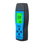
Composition, technical characteristics, and usage methods of pointer clamp ammeters
(1) Composition of clamp ammeter
The clamp type ammeter used to measure AC current mainly consists of a current transformer, rectification circuit, magnetoelectric ammeter, range conversion switch, and measurement circuit, as shown in Figure 1. The iron core of its transformer has a movable part at the upper end of the clamp meter and is connected to the handle. When using, press the handle to open the movable iron core, place the wire with the measured current in the clamp, and then release the handle to close the iron core. At this point, the current carrying conductor is equivalent to the primary winding of the transformer, and the magnetic flux in the iron core generates induced current in the secondary winding. After passing through the rectification circuit, the ammeter indicates the value of the measured current.
The clamp type ammeter used to measure AC and DC currents is composed of an electromagnetic measurement mechanism. The wire with the measured current in the iron core mouth is equivalent to a fixed coil in an electromagnetic measurement mechanism, generating a magnetic field inside the iron core. The movable iron plate located in the middle of the iron core gap is deflected by this magnetic field, which drives the pointer to indicate the value of the measured current.
(2) The use of clamp ammeters
① Clamp type ammeters have low accuracy levels and are commonly used in situations where measurement requirements are not high.
② Before measurement, the corresponding measurement range should be selected based on the current size of the circuit being measured; When the current of the circuit being tested is difficult to estimate, the range switch should be set to the maximum measurement range.
③ There are usually multiple scales on the dial of a clamp type ammeter, and when measuring, the scale corresponding to the range switch should be selected.
④ The selected range should enable the pointer to indicate at least 1/2 to 2/3 of the scale scale to reduce measurement errors.
⑤ When the measured frequency is low or the sine wave has significant distortion, the error of the clamp ammeter is relatively large.
⑥ When the measured current is small and the meter head cannot display, the measured wire can be wound back and forth in the clamp for several more turns. The measured data only needs to be divided by the number of turns made in the clamp to reflect the measured current value.
⑦ After the measurement is completed, the range switch of the clamp ammeter should be set to the highest measurement range.