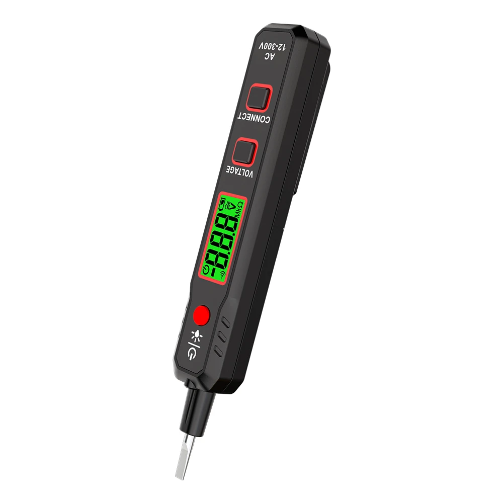
Description of the Principle and Applications of the Voltage Tester Pen
A voltage tester pen is one of the tools widely used by electricians to judge whether an object is electrified. Its internal structure consists of a bulb with two electrodes filled with neon gas, commonly known as a neon bulb. One electrode is connected to the probe tip, and the other electrode is connected to the other end of the pen in series with a high-value resistor. When the voltage between the two electrodes of the neon bulb reaches a certain value, glow occurs between the electrodes. The brightness of the glow is proportional to the voltage between the two electrodes. When the voltage of a live object to ground exceeds the initial glow voltage of the neon bulb, and the probe tip of the voltage tester pen touches the live object, the other end is grounded through the human body, so the tester pen lights up. The resistor in the voltage tester pen functions to limit the current passing through the human body to avoid danger.
Besides judging whether an object is electrified, the voltage tester pen has the following applications:
(1) It can be used for low‑voltage phase verification to check whether any two conductors in the circuit are in the same phase or different phases. The specific method: stand on an object insulated from the ground, hold one voltage tester pen in each hand, and test the two conductors to be measured. If both tester pens glow brightly, the two conductors are of different phases; otherwise, they are the same phase. The judgment is based on the principle that the voltage difference between the two electrodes of the neon bulb in the tester pen is proportional to its luminous intensity.
(2) It can distinguish alternating current (AC) from direct current (DC). During testing with the voltage tester pen, if both electrodes inside the neon bulb light up, it is alternating current; if only one electrode lights up, it is direct current.
(3) It can identify the positive and negative poles of direct current. Connect the voltage tester pen to a DC circuit for testing. The glowing electrode of the neon bulb is the negative pole, and the non‑glowing electrode is the positive pole.
(4) It can detect DC grounding faults. In a DC system insulated from ground, stand on the ground and touch the positive or negative pole of the DC system with the voltage tester pen. If the neon bulb does not light up, there is no grounding fault. If the neon bulb lights up, a grounding fault exists. If the glow appears at the probe tip, it indicates positive pole grounding; if the glow appears at the finger contact end, it indicates negative pole grounding. However, it must be noted that this method cannot be used to judge grounding faults in DC systems equipped with ground‑fault monitoring relays.