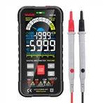
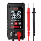
Digital Multimeter Operation Guide
DC Voltage Measurement
1. Insert the black meter pen into the COM jack and the red meter pen into the V/Ω jack.
2. Place the function switch in the DC voltage gear V-range range, and connect the test pen to the power supply to be measured (open circuit voltage) or load (load voltage drop), the polarity of the red pen connected to the end of the red pen will be displayed on the display at the same time.
Note:
1. If you do not know the measured voltage range. Set the function switch to the maximum range and gradually decrease.
2. If the display only shows "1", it means that it is over-range and the function switch should be placed in a higher range.
3. " " means do not measure voltages higher than 1000 V. It is possible to display higher voltage values but there is a risk of damage to the internal wiring.
4. When measuring high voltages, take extra care to avoid electric shock.
DC Current Measurement
1. Insert the black meter pen into COM jack, when measuring the maximum value of 200mA current, the red meter pen is inserted into mA jack, when measuring the maximum value of 20A current, the red meter pen is inserted into 20A jack.
2. Place the function switch in DC current gear A-range, and connect the test pen in series to the load to be measured, the current value will be displayed at the same time, the polarity of the red pen will be displayed.
Attention:.
1. If you don't know the range of current to be measured before use, put the function switch to the maximum range and gradually decrease.
2. If the display only shows "1", it means that it is over-range and the function switch should be placed at a higher range.
3. The maximum input current is 200mA, excessive current will burn out the fuse, should be replaced, 20A range without fuse protection, measurement should not exceed 15 seconds.
AC Voltage Measurement
1. Insert the black pen into the COM jack and the red pen into the V/Ω jack.
2. Place the function switch in the AC voltage range V ~ range, and connect the test pen to the power supply or load to be tested. The test connection diagram is the same as above. There is no polarity display when measuring AC voltage.
Attention: 1.
1. Refer to DC voltage note 1.2.4.
2. " " means do not input voltage higher than 700Vrms, display higher voltage value is possible, but there is a danger of damaging the internal wiring.
Measurement of AC current
1. Insert the black meter pen into COM jack, when measuring the maximum value of 200mA current, the red meter pen is inserted into mA jack, when measuring the maximum value of 20A current, the red meter pen is inserted into 20A jack.
2. Place the function switch in the AC current gear A~ range, and connect the test pen in series to the circuit to be measured.
Note: 1.
1. See DC current DCA measurement Note 1, 2, 3.
Resistance Measurement
1. Insert the black meter pointer into the COM jack and the red meter pointer into the V/Ω jack.
2. Place the function switch in Ω range, and connect the test meter pen to the resistor to be measured.


