Do analog and digital multimeters operate on the same working principle
dissimilarity.
The internal structure of a simulated multimeter includes a meter head, a resistor, and a battery, with the meter head generally using a magneto electric DC microampere meter. Only when measuring resistance, its internal battery needs to be used. The positive terminal of the battery is connected to a black probe, so the current flows out from the black probe and into the red probe. When measuring DC current, a shunt resistor is connected by shifting gears to divert the current. Since the full bias current of the meter is very small, a shunt resistor is used to expand the range. When measuring DC voltage, a resistor is connected in series with the meter head, and different additional resistors are used to achieve conversion between different ranges.
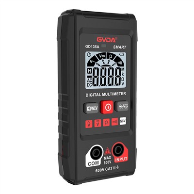
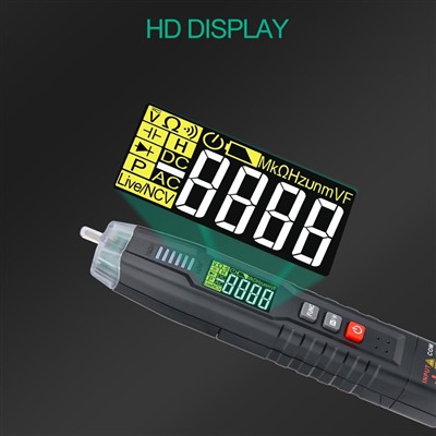
A digital multimeter is composed of a function converter, an A/D converter, an LCD display, a power supply, and a function/range conversion switch, among which the A/D converter generally uses an ICL7106 dual integration type A/D converter. ICL7106 adopts two integrals, the first of which integrates the input analog signal V1, known as the sampling process; The second integration of the reference voltage - VEF integration is called the comparison process. Count two integration processes using a binary counter, convert them into digital quantities, and display them in digital form. To measure AC voltage, current, resistance, capacitance, diode forward voltage drop, transistor amplification factor, and other electrical quantities, corresponding converters must be added to convert the measured electrical quantities into DC voltage signals. Note that the positive pole of the digital multimeter corresponds to the red probe, not the black probe.