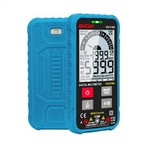
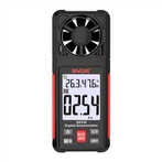
Features of Digital Multimeter and Dual Impedance Digital Multimeter
The basic composition of an ordinary digital multimeter is shown in the figure. Double integral A/D converter is the "heart" of the digital multimeter, through which the analogue - digital conversion. Peripheral circuits mainly include function converter, function and range selector switch, LCD or LED display, in addition to the buzzer oscillator circuit, drive circuit, detection line on and off circuit, low voltage indicator circuit, decimal point and sign (polarity sign, etc.) drive circuit.
A/D converter is the core of the digital multimeter, using a monolithic large-scale integrated circuits 7106. 7106 using the internal heterodyne gate output, can drive the LCD display, power consumption is extremely low. Its main features are: a single power supply, and a wide range of voltages, the use of 9V stacked battery to achieve miniaturisation of the instrument, high input impedance, the use of internal analogue switches to achieve automatic zero and polarity conversion. The disadvantage is that the A/D conversion speed is slow, but can meet the needs of conventional electrical measurements.
Basic knowledge of impedance
The vast majority of digital multimeters sold on the market for measuring industrial, electrical and electronic systems have a very high input loop impedance, generally greater than 1 megohm. This simply means that when the DMM is measuring a loop, it will have little or no effect on the performance of the loop. This is what is needed for most measurement needs, especially for more sensitive electronic or control loops. Previously used troubleshooting tools such as analogue multimeters and solenoid testers typically had low impedance input loops of around 10 kOhm or less. Although such tools are not affected by stray voltages, they are only suitable for measuring power circuits or other applications where low input impedance will not adversely affect or alter the performance of the circuit.
Detecting the Presence or Absence of Voltage
Most electrical technicians and plant maintenance technicians are accustomed to using some type of solenoid tester to determine the presence or absence of power in a loop, which is not fooled by stray voltage due to its low loop impedance. While these testers do serve a purpose, they rarely meet the requirements of the IEC 61010 standard and current North American regulations. Therefore, they should not be used for troubleshooting high energy three-phase switchboards or for measuring whether circuits are live or not. When using a dual impedance meter, the Auto-V/LoZ function can be selected, which has a low input impedance of nearly 3 kOhm. When the test line is placed in an open circuit containing stray voltage, the low input impedance will eliminate the stray voltage and the meter will read near zero, indicating that no voltage is present. However, when the test line is placed on a live loop, the input circuitry will detect the presence of a "hard" voltage and display the actual voltage value present.