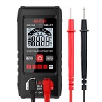
How to find the frequency converter with a multimeter
The frequency converter frequently experiences a variety of issues during routine maintenance, including issues with peripheral circuits, parameter settings, or mechanical failure. Here is a brief introduction on how to determine which aspect of the issue is present if the frequency converter fails.
Static testing
Verify the rectifier circuit, first. Locate the P and N terminals of the DC power supply inside the inverter, set the resistance on the multimeter to the X10 level, and then connect the red and black meter sticks to P, R, S, and T, respectively. There should be roughly tens of balanced, European resistance forces. On the other hand, when the red meter lead is connected to R, S, and T in that order, there is a resistance that is almost infinite when the black meter lead is connected to the P terminal. Repeat the previous instructions while connecting the red meter stick to the N terminal; you ought to receive the same outcome.
The following findings can be used to determine whether a circuit is abnormal:
A. The three-phase resistance is out of balance, which may be an indication that the rectifier bridge has failed.
B. The resistance is infinite when the red meter stick is connected to the P line, indicating that either the rectifier bridge or the beginning resistor is malfunctioning.
2. Inverter circuit testing. Connect the meter's black hand to U, V, and W, respectively, and the red hand to the P terminal. The reverse phase should have an infinite resistance, with each phase's resistance being in the tens of ohms range. To acquire the same result, connect the black meter lead to the N terminal and repeat the previous procedures. If you don't, the inverter module is probably broken. Dynamic exam 2. When the results of the static test are satisfactory, the test machine can be powered on to conduct the dynamic test. Prior to and following power-on, the following details must be taken into consideration:
1. Verify that the input voltage is correct before turning on the device. Explosions will occur when a 380V power supply is linked to a 220V inverter (frying capacitors, varistors, modules, etc.).
2. Verify that the inverter's broadcast ports are correctly connected and that the connection is not loose. The inverter may occasionally malfunction due to abnormal connections, and in extreme circumstances, the machine may blow up.
3. After powering on, check the fault display content to discover the fault and its preliminary cause.
4. If no error is indicated, check the parameters to see if they are abnormal. If so, reset them, start the inverter without a load (i.e., unconnected from the motor), and measure the U, V, and W three-phase output voltage values. Phase loss, three-phase unbalance, etc. indicate a problem with the module or driver board.
5. Perform a load test if the output voltage is normal (no phase loss, three-phase balance). It is ideal to test at maximum load.
Fault judgment
1. Grid voltage or an internal short circuit typically damage the rectifier module. Replace the rectifier bridge if the internal short circuit has been ruled out. Focus on inspecting the user's power grid while addressing defects on the spot, including grid voltage, the existence of equipment that pollutes the grid, such as electric welding machines, etc.
2. Drive circuit failure and motor or cable damage are the two main causes of inverter module damage. Replace the module after the drive circuit has been fixed and the drive waveform has been verified to be sound. In field service, it is important to examine the motor and the associated connections after replacing the driver board. Run the inverter after making sure there is no malfunction.
3. Damage to the soft charging circuit or to the switching power supply, which results in no DC power in the DC circuit, is the usual reason of no display after power-on. The panel might also be harmed if the starting resistor is compromised.
4. The input phase loss, aging circuit, and damp circuit board are typically the causes of the overvoltage or undervoltage indicated after power-on. Replace the damaged device after determining its voltage detection circuit and detection point.
5. It displays over-current or a ground short-circuit at power-up, which is typically the result of damage to the current detecting circuit. such operational amplifiers, Hall elements, etc.
6. Damage to the driving circuit or inverter module is typically the root cause of the start-up display overcurrent.
7. The output voltage is normal with no load, however after loading, it displays overload or overcurrent. This condition is typically brought on by incorrect parameter setting, driving circuit aging, or module breakage.