Capacitors are one of the most frequently used electronic components in electronics, but many people do not know how to detect capacitors. Below we introduce several methods to test capacitors with a multimeter. Capacitors are one of the most commonly used electronic components. The common word symbol for capacitors is "C". Capacitors are mainly composed of metal electrodes, dielectric layers and electrode leads, and the two electrodes are insulated from each other. Therefore, it has the basic performance of "blocking DC to AC".


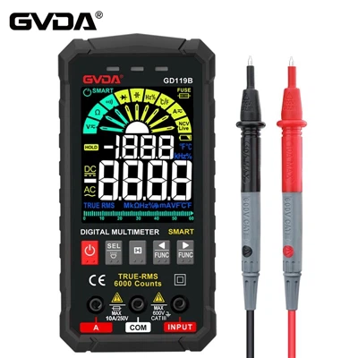
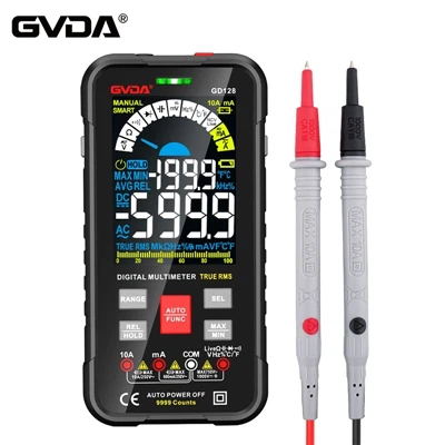
Use a digital multimeter to test capacitors as follows:
1. Direct detection with capacitive gear
Some digital multimeters have the function of measuring capacitance, and their ranges are divided into five ranges: 2000p, 20n, 200n, 2μ and 20μ. When measuring, the two pins of the discharged capacitor can be directly inserted into the Cx jack on the meter board, and the displayed data can be read after selecting the appropriate range.
000p level, suitable for measuring capacitance less than 2000pF; 20n level, suitable for measuring capacitance between 2000pF and 20nF; 200n level, suitable for measuring capacitance between 20nF and 200nF; 2μ level, suitable for measuring between 200nF and 2μF 20μ range, suitable for measuring capacitance between 2μF and 20μF.
Experience has proved that some types of digital multimeters (such as DT890B+) have large errors when measuring small-capacity capacitors below 50pF, and there is almost no reference value for measuring capacitors below 20pF. At this time, the series method can be used to measure the small value capacitance. The method is: first find a capacitor of about 220pF, use a digital multimeter to measure its actual capacity C1, and then connect the small capacitor to be measured in parallel with it to measure its total capacity C2, then the difference between the two (C1-C2) is The capacity of the small capacitor to be measured. Using this method to measure small-capacity capacitors of 1 to 20pF is very accurate.
2. Detect with resistance gear
Practice has proved that the charging process of the capacitor can also be observed by using a digital multimeter, which is actually a discrete digital quantity to reflect the change of the charging voltage. Assuming that the measurement rate of the digital multimeter is n times per second, while observing the charging process of the capacitor, n independent and sequentially increasing readings can be seen every second. According to this display feature of the digital multimeter, the quality of the capacitor can be detected and the size of the capacitance can be estimated. Introduced below is the method of detecting capacitors by using the resistance gear of a digital multimeter, which is very useful for instruments without capacitance gears. This method is suitable for measuring large-capacity capacitors ranging from 0.1 μF to several thousand microfarads.
1. Measurement operation method
As shown in the figure, turn the digital multimeter to the appropriate resistance gear, and the red test lead and black test lead respectively contact the two poles of the capacitor Cx under test. At this time, the displayed value will gradually increase from "000" until the overflow symbol "1" is displayed. If it always displays "000", it means that the capacitor is short-circuited; if it always displays overflow, it may be an open circuit between the internal poles of the capacitor, or the selected resistance file may be inappropriate. When checking electrolytic capacitors, it should be noted that the red test lead (with positive charge) is connected to the positive electrode of the capacitor, and the black test lead is connected to the negative electrode of the capacitor.
2. Measurement principle
The measurement principle of measuring capacitor with resistance gear is shown in Figure 5-11(b). During measurement, the positive power supply charges the capacitor Cx to be measured through the standard resistor R0, and at the moment of charging, because Vc = 0, "000" is displayed. As Vc gradually increases, the displayed value increases. When Vc = 2VR, the meter starts to display overflow symbol "1". The charging time t is the time required for the display value to change from "000" to overflow, and this time interval can be measured by a quartz watch.
3. Use a digital multimeter to estimate the measured data of the capacitance
When using the DT830 digital multimeter to estimate the capacitance of a capacitor from 0.1μF to several thousand microfarads, you can select the resistance level according to Table 5-1. The table shows the range of the measurable capacitance and the corresponding charging time. The data listed in the table also has reference value for other types of digital multimeters.
The principle of selecting the resistance range is: when the capacitance is small, the high resistance should be selected, and when the capacitance is large, the low resistance should be selected. If the high-resistance gear is used to estimate large-capacity capacitors, the charging process is very slow, and the measurement time will last for a long time; if the low-resistance gear is used to check small-capacity capacitors, the meter will always display overflow due to the extremely short charging time, and the change process cannot be seen. .
3. Detect with voltage gear
Detecting capacitors with the DC voltage range of a digital multimeter is actually an indirect measurement method. This method can measure small-capacity capacitors ranging from 220pF to 1μF, and can accurately measure the leakage current of the capacitors.
1. Measurement method and principle
The measurement circuit is shown in the figure, E is an external 1.5V dry battery. Turn the digital multimeter to DC 2V, the red test lead is connected to one electrode of the capacitor Cx under test, and the black test lead is connected to the negative electrode of the battery. The input resistance of 2V gear is RIN=10MΩ. After the power is turned on, the battery E charges Cx through RIN and starts to build up the voltage Vc. The relationship between Vc and charging time t is:

Here, since the voltage across RIN is the input voltage VIN of the instrument, RIN actually also functions as a sampling resistor. Obviously, VIN(t)=E-Vc(t)=Eexp(-t/RINCx) (5-2)
Fig. Variation curve of input voltage VIN(t) and charging voltage Vc(t) on the measured capacitor. It can be seen from the figure that the change process of VIN(t) and Vc(t) is exactly opposite. The change curve of VIN(t) decreases with time, while Vc(t) increases with time. Although the instrument shows the change process of VIN-(t), it indirectly reflects the charging process of the measured capacitor Cx. During the test, if Cx is open circuit (no capacity), the displayed value is always "000"; if Cx is short-circuited internally, the displayed value is always the battery voltage E, which does not change with time.

It shows that when the circuit is just turned on, t=0, VIN=E, the initial value displayed by the digital multimeter is the battery voltage, and then with the increase of Vc(t), VIN(t) gradually decreases until VIN=0V, Cx The charging process ends, at this time Vc(t)=E.
Using a digital multimeter to detect capacitors in the voltage range can not only check small-capacity capacitors ranging from 220pF to 1μF, but also measure the leakage current of the capacitors at the same time. Let the leakage current of the capacitor to be measured be ID, and the last stable value displayed by the meter is VD (unit is V), then Id=Vd/Rin.
2. example example
Example 1: The measured capacitance is a 1μF/160V fixed capacitor, and the 2VDC range of the DT830 digital multimeter is used (RIN=10MΩ). Connect the circuit according to Figure 5-12. At first, the meter displayed 1.543V, and then the displayed value gradually decreased. After about 2 minutes, the displayed value stabilized at 0.003V. Based on this, the leakage current of the capacitor under test can be obtained

The leakage current of the capacitor under test is only 0.3nA, indicating good quality.
Example 2: The capacitor to be tested is a 0.022μF/63V polyester capacitor, and the measurement method is the same as Example 1. Due to the small capacity of this capacitor, VIN(t) drops rapidly during measurement, and the displayed value drops to 0.002V after about 3 seconds. Substitute this value into Equation (5-3), and calculate the leakage current to be 0.2nA.
3. Precautions
(1) Before measuring, the two pins of the capacitor should be short-circuited and discharged, otherwise the change process of the reading may not be observed.
(2) Do not touch the capacitive electrodes with both hands during the measurement process to avoid the meter jumping.
(3) During the measurement process, the value of VIN(t) changes exponentially, and it decreases rapidly at the beginning, and as time goes on, the decreasing speed becomes slower and slower. When the capacity of the measured capacitor Cx is less than a few thousand picofarads, the initial display value of the meter is lower than that of the battery because VIN(t) drops too fast at first, and the measurement rate of the meter is too low to reflect the initial voltage value. voltage E.
(4) When the measured capacitor Cx is greater than 1μF, in order to shorten the measurement time, the resistance profile can be used for measurement. However, when the capacity of the capacitor under test is less than 200pF, it is difficult to observe the charging process due to the brief change in the reading.
4. Use the buzzer to detect
Using the buzzer gear of the digital multimeter, you can quickly check the quality of electrolytic capacitors. The measurement method is shown in Figure 5-14. Turn the digital multimeter to the buzzer gear, and use two test pens to contact the two pins of the capacitor Cx under test respectively. A short beep should be heard, then the sound will stop, and the overflow symbol "1" will be displayed at the same time. Then, swap the two test leads for another measurement, the buzzer should sound again, and finally display the overflow symbol "1". This situation indicates that the measured electrolytic capacitor is basically normal. At this time, you can dial to the 20MΩ or 200MΩ high-resistance gear to measure the leakage resistance of the capacitor to judge whether it is good or bad.