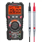
How to use a digital multimeter to measure the quality of inductive components?
Step 1: Detect gear selection.
Since the DC impedance of the copper wire of the inductance coil is very small, it is basically close to straight-through. Therefore, when using a digital multimeter to detect inductive components, according to this characteristic, select the lowest gear of resistance, and judge whether it is good or bad by measuring its on/off method.
Turn the digital multimeter to the position marked with the symbol "n", and select the range position of "diode with buzzer".
The second step: detection operation.
In the "passive" state after the mainboard of the notebook computer is powered off, use the two test leads of the digital multimeter to touch the solder joints at both ends of the inductance element respectively. Since the inductance element has no positive and negative distinctions, the test leads are not divided into positive and negative. During this step of operation, the time for the test lead to touch the solder joints at both ends of the inductance element should not be too short, otherwise it is easy to cause misjudgment.
Step 3: Observe the test results and make a judgment.
If the reading displayed on the LCD screen is a stable "0" or very close to "0", and the buzzer keeps ringing during the test, the tested inductive element is good; if the reading is displayed as an overflow symbol " 1" (that is, "∞"), it indicates that the inductance element has been broken; if the number displayed on the LCD screen flickers during the test; the buzzer rings sometimes but does not sound, most of the time it is the solder joint of the element If there is a phenomenon of virtual welding or desoldering, it should be repaired and then tested. The above three situations are relatively common in maintenance and inspection, and there are two other special situations that need to be specially explained, such as F:
First, if the reading of the digital meter is too large to about 10n or above 10Ω, even if the buzzer keeps beeping, it cannot be judged that the inductance element under test is good. Because the impedance of all inductive components on the motherboard of the notebook computer cannot reach about 10Ω: the copper wires of the windings of the flat energy storage inductors, transformers, etc. used in the power circuit with large power consumption and large current are relatively thick, and the impedance is very high. Low; small-volume chip inductors used in power circuits with low power consumption and low current or signal circuits. Although the copper wire of the winding is very thin, the number of turns is small, the length is short, and the impedance is also very low. Therefore, the detected reading of about 10Ω or above is not the normal impedance value of the inductance element. It may be that the measured inductance has been disconnected, and the reading is the impedance value of other parallel circuits; it may also be that the measured inductance has been burned. The contact resistance value formed by the short circuit between them.
Second, if during the detection process, the buzzer only makes a short sound when the test lead touches the solder joints at both ends of the inductor and then stops abruptly. This usually occurs in a power circuit with a large current. This kind of phenomenon not only means that the inductance element has been broken, but also shows that there is a serious short circuit (grounding) phenomenon in the circuit at one end of the inductance. of. Therefore, when testing the inductance element, the time for the probe to touch the solder joints at both ends of the inductance element should not be too short.


