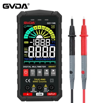
How to use a multimeter to detect common electronic components?
Whenever the circuit board can not operate according to the normal conditions, after checking the circuit and there is no problem, it is very likely that an electronic component is broken at this time. If you want to repair it, you must find the problematic component and replace it, but the problematic component is found It is a technical job and has certain skills. Today I will teach you how to use a multimeter to detect some commonly used electronic components.
Resistance detection
The most direct way to detect resistance is to use the multimeter resistance file to measure. Generally, the resistance size will be marked on the resistance. Select the appropriate resistance file and connect the red and black test leads to both ends. If the reading is close, it is normal, otherwise it is broken. When making resistance, be careful not to touch the red and black test leads with both hands. It is not dangerous, but to ensure the accuracy of the resistance measurement. It is ok to touch one of the test leads with your hands.
Fixed Capacitor Detection
In addition to using a multimeter to select the appropriate range of the capacitance block to measure the capacitance value, you can also use the resistance file to measure. When measuring, choose the appropriate resistance file. Use two test leads to connect the two pins of the capacitor. The resistance value should be infinite. If If the resistance value is 0, the capacitor is damaged.
Electrolytic Capacitor Detection
The measurement method of electrolytic capacitor is a little different from that of fixed capacitor. Of course, you can choose to use capacitive block to detect. Everyone knows this. Let me talk about the method of using electric block to measure. First, choose the appropriate resistance file, and the red test lead and black test lead respectively touch the capacitor. Two poles, at this time, the displayed value will increase from 0 until the overflow symbol 1 is displayed. If it always displays 0, it means that the capacitor is short-circuited inside. If it always displays 1, it means that the capacitor is open. It should be noted that when measuring, because the electrolytic capacitor has positive and negative poles, it must not be reversed here. Usually, the red test lead is connected to the anode of the capacitor (the one with long legs), and the black test lead is connected to the cathode of the capacitor (the one with short legs). , the pointer multimeter is just the opposite.
Inductance detection
Also select the resistance gear of the multimeter, and connect the test leads to both ends of the inductor. If the measured resistance value is zero, the inductor is short-circuited internally. Under normal circumstances, the DC resistance of the measured inductor is the same as the diameter of the enameled wire used to wind the inductor coil, and the wire winding coil. The number has a direct relationship, as long as the resistance value can be measured, the inductance can be considered normal.
Diode detection
Adjust the multimeter to the detection diode gear, connect the anode of the diode with the red test lead, and connect the cathode of the diode with the black test lead. If the voltage drop of the diode is displayed on the display screen (usually 0.5 for the silicon tube and 0.2 for the germanium tube), it means that the diode is normal. Replace the test leads , if the display shows 1, it is normal, otherwise it is broken down, if the two test results are 0 or 1, it means that the diode is damaged.
LED detection
Also adjust the digital multimeter to the detection diode block, touch the anode of the light-emitting diode with the red test lead, and touch the cathode of the light-emitting diode with the black test lead (same as the diode above), if you see it glowing, it means normal, otherwise it is damaged.