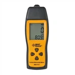
How to use digital multimeter and measure skills
1. Judging whether the circuit or device is charged or not:
The AC voltage block of the digital multimeter is very sensitive, even if there is a small induced voltage around it, it can be displayed. According to this feature, it can be used as a test pencil. The usage is as follows: Turn the multimeter to AC20V gear, hang the black test lead in the air, hold the red test lead in contact with the side line or device, then the multimeter will display, if the displayed number is between a few volts and more than ten volts (different multimeters will There are different displays), indicating that the line or device is charged, and if the display is zero or very small, it indicates that the line or device is not charged.
Second, distinguish whether the power supply line is live or neutral:
The first method: You can use the above method to judge: the one with the larger number is the live line, and the one with the smaller number is the zero line. This method requires contact with the line or device being measured.
The second method: No contact with the measured line or device is required. Turn the multimeter to the AC2V gear, hang the black test lead in the air, and hold the red test lead to slide the tip along the line gently. At this time, if the meter shows a few volts, it indicates that the line is live. If the display is only a few tenths of a volt or even less. It means that the line is the zero line. Such a judgment method is not in direct contact with the line. Not only safe but also convenient and fast.
3. Find the breakpoint of the cable: When there is a breakpoint in the cable, the traditional method is to use a multimeter to block and find the breakpoint of the cable section by section. This is not only a waste of time, but also damages the cable to a large extent. insulation. The disconnection point of the cable can be found quickly by using the inductive characteristic of the digital multimeter. First use the electric barrier to determine which cable core wire is open circuited. Then connect one end of the broken core wire to the AC220V power supply, and then turn the multimeter to the AC2V gear position, hang the black test lead in the air, hold the red test lead and slide the tip along the line gently, at this time, if the meter shows How many Volts or a few tenths of volts (different due to different cables), if the display on the meter suddenly drops a lot when moving to a certain position, write down this position: under normal circumstances. The breakpoint is between 10 and 20 cm in front of this position.
This method can also be used to find the breaking point of resistance wires such as faulty electric blankets.
Fourth, measure the frequency of UPS power supply: for UPS power supply. The stability of the voltage at its output terminal is an important parameter, and the frequency of its output is also very important. However, it cannot be measured directly with the frequency block of the digital multimeter, because the voltage that the frequency block can withstand is very low. Only a few volts. At this time, a 220V/6V or 220V/4V step-down transformer can be connected to the output terminal of the UPS power supply to reduce the voltage without changing the frequency of the power supply, and then connect the frequency block to the output of the transformer to measure the UPS power supply. Frequency of.
5. Use a digital multimeter to test whether the triode is good or bad: use a diode to measure that one pin is connected to the other two pins, but those two pins are not connected (for a digital meter, if the pin that is common to the other two pins is connected It is a red pen, then this is an NPN tube, if it is connected to a black pen, then this is a PNP tube. If a pointer meter is used, it is just the opposite.), this pin is the base set B, and B is its A tube has been blown. (Not available with internal protection diode.)
If the voltage drop measured by the diode file is greater than 0.5V, then this is a silicon tube, if it is around 0.2V, this is a germanium tube.
Then put the measured triode into the HFE jack according to the pins, and switch to the HFE gear to measure the DC magnification. (Only valid for ordinary low-power tubes, not valid for high-power tubes, because high-power tubes need a large driving power for the base, but the multimeter cannot provide it.) Generally, the DC magnification HFE of low-power tubes is 30-1000 The voltage drop measured on one of the pins is a few millivolts larger than the other pin, then this pin is the emitter E, and the remaining voltage drop is a few millivolts smaller than the collector C. If you use a diode file to measure If any two pins of the tube are connected, then the tube has been broken down and damaged. If it doesn't work, then use the diode test method with a digital multimeter to measure a diode with a digital multimeter. When it is turned on, it will be displayed as zero or one point. When the table is exchanged again (that is, when the deadline is reached), it is displayed as 1. When 1 is displayed, the black test lead is connected to the positive pole of the diode, while the red test lead is connected to the negative pole of the diode. If it doesn't stop then it must be a bad diode. If the result of the two measurements is 1, the test diode is open. If the two measured results are a few tenths or both, the diode has broken down.
The comb multimeter has a gear for detecting diodes. First, pull the gear switch to this gear, connect the red pen to one leg, and the black pen to the other two pins. If both are connected, it is a PNP type, and the red pen is connected to it. It is the base, if both of them are not connected, there are two cases, 1. When the test pen is adjusted, both sides are connected, it is NPN, and the red pen is connected to the base. , after the adjustment, it is the base.
The red test pen is connected to any pin, and the black pen touches the other two pins. One is connected and the other is not.
Detect triode (use "diode file")
Positive test: the red pen is connected to the positive pole, and the black pen is connected to the negative pole, which can display the forward voltage drop of the PN junction. Normally it should display: silicon tube 0.500~0.700 germanium tube 0.150~0.300
Reverse test: connect the black pen to the positive pole, and the red pen to the negative pole. Normally, it should display: "1"
Positive test and negative test are both 0 or 1, indicating that the tube is damaged
According to the above-mentioned method of detecting a diode, a triode is detected. First determine the collector C and the emitter E, and use the meter to measure the forward voltage drop of the two PN junctions. The one with the smaller voltage drop is the collector C, and the one with the larger voltage drop is the emitter E. The common pole used for the two measurements is Red pen, this tube is NPN type, the public pole is black pen, this tube is PNP type.