In the process of building a switching power supply, how should the filter capacitor be properly selected?
The filter capacitor plays a very important role in the switching power supply. How to correctly select the filter capacitor, especially the selection of the output filter capacitor is a problem that every engineer and technician is very concerned about. We can see various capacitors on the power filter circuit, 100uF, 10uF, 100nF, 10nF with different capacitance values, so how are these parameters determined? Don't tell me that I copied someone else's schematic diagram, huh, huh.
For common electrolytic capacitors used in 50Hz power frequency circuits, the pulsating voltage frequency is only 100Hz, and the charging and discharging time is on the order of milliseconds. In order to obtain a smaller pulsation coefficient, the required capacitance is as high as hundreds of thousands of μF. Therefore, the goal of ordinary low-frequency aluminum electrolytic capacitors is to increase the capacitance. The main parameters of pros and cons. However, the output filter electrolytic capacitor in the switching power supply has a sawtooth wave voltage frequency as high as tens of kHz, or even tens of MHz. At this time, the capacitance is not the main indicator. The standard for measuring the quality of high-frequency aluminum electrolytic capacitors is "impedance- "Frequency" characteristics, it is required to have a lower equivalent impedance within the operating frequency of the switching power supply, and at the same time have a good filtering effect on the high-frequency spikes generated when the semiconductor device is working.
Ordinary low-frequency electrolytic capacitors begin to show inductivity at around 10kHz, which cannot meet the requirements of switching power supplies. The high-frequency aluminum electrolytic capacitor dedicated to the switching power supply has four terminals. The two ends of the positive aluminum sheet are respectively drawn out as the positive electrode of the capacitor, and the two ends of the negative aluminum sheet are also respectively drawn out as the negative electrode. The current flows in from one positive terminal of the four-terminal capacitor, passes through the inside of the capacitor, and then flows from the other positive terminal to the load; the current returning from the load also flows in from one negative terminal of the capacitor, and then flows from the other negative terminal to the negative terminal of the power supply.
Since the four-terminal capacitor has good high-frequency characteristics, it provides an extremely favorable means for reducing the pulsating component of the voltage and suppressing the switching spike noise. High-frequency aluminum electrolytic capacitors also have a multi-core form, that is, the aluminum foil is divided into several shorter sections, and multiple leads are connected in parallel to reduce the impedance component in the capacitive reactance. And the use of low-resistivity materials as lead-out terminals improves the ability of the capacitor to withstand large currents.
For digital circuits to operate stably and reliably, the power supply must be "clean", and energy replenishment must be timely, that is, filtering and decoupling must be good. What is filtering and decoupling, simply put, it is to store energy when the chip does not need current, and I can replenish energy in time when you need current. Don't tell me that this responsibility is not for DCDC and LDO? Yes, at low frequencies they can handle it, but high speed digital systems are different.
Let's take a look at the capacitor first. The function of the capacitor is simply to store the charge. We all know that capacitor filtering should be added to the power supply, and a 0.1uF capacitor should be placed on the power pin of each chip for decoupling, etc. Why do I see that the capacitor next to the power pin of some board chips is 0.1uF or 0.01uF Yes, what's the point? To understand this truth, we must understand the actual characteristics of capacitors. An ideal capacitor is just a storage of charge, namely C. However, the actual manufactured capacitor is not so simple. When analyzing the integrity of the power supply, the commonly used capacitor model is shown in the figure below.
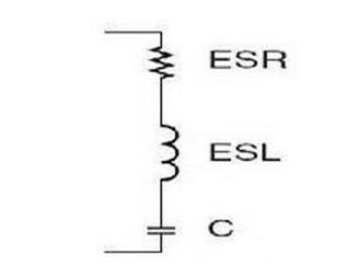
In the figure, ESR is the series equivalent resistance of the capacitor, ESL is the series equivalent inductance of the capacitor, and C is the real ideal capacitor. ESR and ESL are determined by the manufacturing process and materials of the capacitor and cannot be eliminated. What effect do these two things have on the circuit. ESR affects the ripple of the power supply, and ESL affects the filter frequency characteristics of the capacitor.
We know that the capacitive reactance Zc=1/ωC of the capacitor, the inductive reactance Zl=ωL of the inductor, (ω=2πf), and the complex impedance of the actual capacitor is Z=ESR+jωL-1/jωC=ESR+j2πf L-1/j2πf c. It can be seen that when the frequency is very low, the capacitance plays a role, and when the frequency is high to a certain level, the role of the inductance cannot be ignored, and when the frequency is higher, the inductance will play a leading role. The capacitor loses its filtering effect. So remember, when the frequency is high, the capacitor is not just a capacitor.
As mentioned above, the equivalent series inductance of the capacitor is determined by the manufacturing process and material of the capacitor. The ESL of the actual chip ceramic capacitor ranges from a few tenths of nH to several nH, and the smaller the package, the smaller the ESL.
From the filter curve of the capacitor above, we can also see that it is not flat, it is like a 'V', that is to say, it has frequency-selective characteristics, and we hope that it is as flat as possible (pre-stage board-level filtering), And sometimes you want it to be as sharp as possible (filtering or notching). What affects this characteristic is the quality factor Q of the capacitor, Q=1/ωCESR, the larger the ESR, the smaller the Q, and the flatter the curve. On the contrary, the smaller the ESR, the larger the Q, and the sharper the curve. Usually, tantalum capacitors and aluminum electrolytics have relatively small ESL, but ESR is large, so tantalum capacitors and aluminum electrolytics have a wide effective frequency range, which is very suitable for the front-end board level filter. That is to say, a large-capacity tantalum capacitor is often used for filtering at the input stage of DCDC or LDO. And put some 10uF and 0.1uF capacitors near the chip for decoupling, ceramic capacitors have very low ESR.