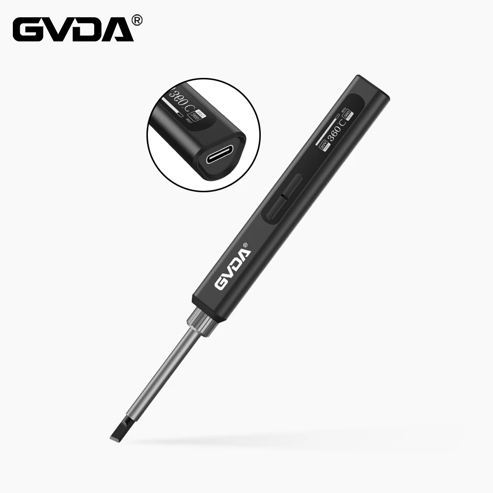
Introduction to welding - basic knowledge of electric soldering iron
Commonly used devices:
(1) Device types: resistors, capacitors, LEDs, MOS tubes, various chips, headers, pin headers, buttons, USB, etc. (roughly divided into pins and patches).
(2) Polarity judgment:
a. Resistors and non-polar capacitors have no positive and negative poles, such as monolithic capacitors, ceramic capacitors, and all resistors. No need to distinguish.
b. Some capacitors have polarity (mainly electrolytic capacitors), which needs attention. For example, aluminum electrolytic capacitors. Such capacitors are available in both cylindrical and chip types.
Distinguishing method:
1. There will be polarity signs on the surface of the capacitor, just look for them.
2. Pin length, long plus, short minus
3. The end with the black edge is the negative pole
4. Tantalum capacitor, the one with colored edge is the positive electrode (note to distinguish it from 3, reverse connection will cause explosion)
5. It can also be measured. The principle is: when the forward voltage is applied to the electrolytic capacitor, the leakage current is small and the resistance is large; vice versa: the leakage current is large and the resistance is small. When the red test lead is connected to one end and the other end, the resistance measured, the larger end is the positive pole.
c. LED positive and negative polarity judgment:
1. Look at the length of the pins, long is positive and short is negative.
2. The direction that T or the triangle points to is the negative pole, or the one with a green mark (the side with the mark is the negative pole)
c. Transistor, please refer to the data sheet to see its three poles.
e. Chip polarity judgment:
1. There will be a dot on the pad, and there will also be a dot on the chip, in the upper left corner, and the pin on the left corresponding to the dot is pin 1. If there is no point, look at the side and there will be a gap, so that the gap faces the point on the pad.
Welding method:
a. First place the soldering tin on one or two pads of the component to be soldered, and then after melting, place one end or two legs of the component on it, fix it first, and then solder the other legs.
b. When soldering a device with dense pins, don't be afraid of the pins sticking in the early stage. After the initial tin application, apply solder paste and use a soldering iron to remove the excess solder and make the solder round (recommended) blade soldering iron).
c. If tin is accidentally stuck to other places, it doesn't matter. Just use a flat-head soldering iron and scrape it off. (Don't use too much force)
d. When welding the socket or patching, use a soldering iron to heat the pad and then tin it.
e. To remove the tin from the via holes, use a solder suction device, heat it with an electric soldering iron, and just suck it up with the solder suction device.
f. Solder paste can also be used to remove the tip.