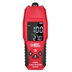
Multimeter composition structure
1. Header
1) Pointer gauge
It is a high-sensitivity magnetoelectric DC ammeter, and the main performance indicators of the multimeter basically depend on the performance of the meter head. The sensitivity of the meter head refers to the DC current value flowing through the meter head when the pointer of the meter head deflects at full scale. The smaller the value, the higher the sensitivity of the meter head. The greater the internal resistance when measuring voltage, the better its performance. There are four scale lines on the meter head, and their functions are as follows:
The first line (from top to bottom) is marked with R or Q, which indicates the resistance value. When the switch is in the ohm block, read this scale line.
The second bar is marked with ~ and VA, indicating the AC, DC voltage and DC current value, when the transfer switch is in the AC, DC voltage or DC current position, and the range is in other positions except AC 10V, read this scale Wire.
The third line is marked with 10V, which indicates the AC voltage value of 10V. When the switch is in the AC and DC voltage range and the measuring range is AC 10V, read this scale line.
The fourth bar, labeled dB, indicates the audio level.
2) digital gauge
The head of a digital multimeter is generally composed of an AD (analog-to-digital) conversion chip + peripheral components + a liquid crystal display. The accuracy of the multimeter is affected by the head. Called 3 1/2 digit multimeter, 4 1/2 digit multimeter and so on. The most commonly used chips are ICL7106 (classic chip with 3.5-digit LCD manual range, and subsequent versions are 7106A, 7106B, 7206, 7240, etc.), ICL7129 (classic chip with 4.5-digit LCD manual range), ICL7107 (3-digit and a half LED manual range Classic Chip).
2. Measurement line
The measurement circuit is a circuit used to convert various measured objects into tiny DC currents suitable for meter measurement. It is composed of resistors, semiconductor elements and batteries. Different ranges, after a series of processing (such as rectification, shunt and voltage division, etc.), the system-turned-quantitative-limited tiny DC current is sent to the meter for measurement.
3. Transfer switch
Its role is to select various measurement lines to meet the measurement requirements of different types and ranges. There are generally two transfer switches, marked with different gears and ranges. ,
4. Test lead and test lead jack.
The test leads are divided into red and black. When using, the red test lead should be inserted into the jack marked with "+", and the bright test lead should be inserted into the jack marked with "-".
Multimeter symbol meaning.
1. Indicates AC, - indicates DC.
2. V - 2.5KV 40002N means that for AC voltage and 2.5KV DC voltage block, the sensitivity is 40002N.
3. A-V- means that current, electricity and resistance can be measured.
4. 45-65-1000Hz means that the frequency range is below 1000Hz, and the standard I frequency range is 45-65Hz.
5. 20002N DC means that the sensitivity of DC block is 20002N.