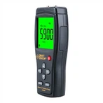
Multimeter test circuit steps-Multimeter troubleshooting circuit boards
The basic principle of a multimeter is to utilize a sensitive magneto-electric DC ammeter (microammeter) as a meter head. When a small current passes through the head, a current is indicated. However, the head can not pass large currents, so the head must be connected in parallel with the series connection of some resistors for shunt or voltage reduction, so as to measure the current, voltage and resistance in the circuit.
1. Select the range: multimeter DC current file labeled "mA" has 1mA, 1omA, 100mA three ranges. Select the range, should be based on the size of the current in the circuit. If you do not know the size of the current, the maximum range should be selected.
2. Measurement method: multimeter should be connected in series with the circuit under test. The corresponding part of the circuit should be disconnected, the multimeter pen connected to the ends of the breakpoint. The red pen should be connected to the breakpoint connected to the positive pole of the power supply, the black pen connected to the breakpoint connected to the negative pole of the power supply.
3. Correct reading: DC current file scale line is still the second, such as the selection of 100mA file, available in the third line of figures, readings can be multiplied by 10.
Multimeter test circuit steps
(1) In the line fault detection, the probe on the test equipment shall not be inserted into any connector or fuse box terminals, otherwise it will cause most of the terminals deformed. The deformation of the terminals will result in poor contact.
(2) After checking the circuit is correct, turn on the power, rotate the potentiometer light-emitting diode brightness will change. Make the light-emitting diode brightness moderate.
(3) will be ready to use the multimeter according to the requirements of the previous talk should be done before, and the selector switch will be placed in the Vl0 volts.
(4) holding the insulating rod of the meter, the positive and negative pens were contacted with the positive and negative poles of the battery box lead lugs, measuring the power supply voltage. Correctly read the voltage value.
Record: the power supply voltage is on the volts.
(5) the multimeter red and black pens contact light-emitting diode pins, measuring light-emitting diode voltage between the poles. Correctly read out the voltage value.
Record: light-emitting diode voltage volts at both ends.
(6) use a multimeter to measure the voltage at the ends of the fixed resistor. First judge the positive and negative pens should be contact position, and then measure.
Record: voltage volts at both ends of the fixed resistor.
In the above three steps in the measurement, which voltage value if less than 2.5 volts, the multimeter selector switch can be changed to V2.5 volts and then measured again, compare the results of the two measurements (change the range should pay attention to the reading of the scale).
(7) Measurement is complete, disconnect the circuit power. According to the previous talk about the multimeter should be done after the use of the requirements of the receipt of the multimeter.