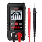
Operating Methods and Protection Measures for Multimeters
This section mainly introduces the functions and operating methods of analog multimeters. Analog multimeters feature intuitive indication and fast‑response measurement. Nevertheless, they have low input resistance and relatively large measurement errors. Therefore, they are generally used for measuring variable voltage and current values. The variation range of voltage and current can be observed from the deflection of the meter pointer.
An analog multimeter mainly consists of a meter movement, measurement circuit components and a selector switch. It comes in two form‑factors: portable and pocket‑size. The scale dial, zero‑adjustment knob and test jacks are mounted on the front panel. Although multimeters vary slightly in available functions, four basic functions are universal: measuring DC current, measuring DC voltage, measuring AC voltage, and measuring AC‑DC resistance. Some multimeters can also measure audio level, AC current, capacitance, inductance and special parameters of transistors. Differences in supported functions lead to variations in physical layout among multimeter models.
To measure multiple electrical quantities with various ranges, the measured quantity must be converted by the internal measurement circuit into DC current acceptable for the moving‑coil meter movement. The more functions a multimeter provides, the more complex its measurement circuit becomes. Resistors are widely used within circuits for current and voltage measurement. Rectifier components are incorporated in the AC‑voltage‑measurement circuit, and dry‑cell batteries serve as the power supply for the DC‑resistance‑measurement circuit.
The selector switch of an analog multimeter is a switching device for selecting different measured quantities and measurement ranges. It comprises several stationary contacts and movable contacts. Circuits are connected when movable contacts close onto stationary contacts. Stationary contacts are commonly called "throws", and movable contacts are referred to as "poles". When operating the selector switch, poles close onto different throws to form distinct measurement circuits. The number of poles and throws varies with switch construction. Typical selector‑switch configurations for multimeters include four‑pole three‑throw, single‑pole nine‑throw, and two‑pole eleven‑throw.