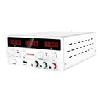
Primary switching power supply test points
When debugging a switching power supply, in addition to using a voltmeter to measure the voltage of the pins of related components in the control circuit, it is more important to use an oscilloscope to observe the relevant voltage waveforms in order to judge whether the switching power supply is in the best working condition. This article mainly explains the selection of oscilloscope test points. For example, when the test point is the output pin of the PWM control chip, an oscilloscope can be used to simultaneously measure the two important parameters of the driving pulse amplitude and duty cycle.
The selection of test points is very important. Reasonable selection of test points can not only ensure the safety of debugging, but also reflect the working status of the switching power supply and simplify the debugging process.
The test point selection of switching power supply is shown in Figure 7-3-1. The test point TP1 is the drain of the MOSFET power switch tube, TP2 is the source of the switch tube, Rs is the current sampling resistor, and TP3 is the negative pole of the primary high-voltage circuit. We can connect the two test points TP1 and TP2 to the two input channels (CH1 and CH2) of the dual-trace oscilloscope, and observe the voltage waveforms of the two points at the same time. At this time, the ground terminals of the two probes should be connected to the negative pole of the primary input DC circuit at the same time, that is, the TP3 position. During the actual measurement, the ground clip of the probe can be clamped directly on the ground pin of Rs.
From TP1, we can see the drain voltage waveform of the power switch tube. This waveform can reflect information such as drain peak voltage, input DC high voltage, secondary reflection voltage, switch tube conduction voltage drop, and conduction and cut-off time. In the single-ended flyback switching power supply, the drain voltage waveform of the power switch tube is shown in Figure 7-3-2.
From TP2, you can see the source voltage waveform of the power switch tube. This waveform is the voltage waveform on the sampling resistor Rs, which can reflect information such as drain current, turn-on and turn-off time. The drain current waveform of the power switch tube is shown in Figure 7-3-3. This waveform reflects that the switching power supply works in continuous current mode. In each cycle, when the switch tube is turned on, the drain current starts to rise from the minimum initial current. Before the switch tube is turned off, the drain current reaches the maximum value.