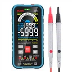
Realization principle of automatic range multimeter
1. Structure of Multimeter (Type 500)
The multimeter is composed of three main parts: meter head, measuring circuit and changeover switch.
(1) Meter head: It is a high-sensitivity magnetoelectric DC ammeter. The main performance indicators of the multimeter basically depend on the performance of the meter head. The sensitivity of the meter head refers to the DC current value flowing through the meter head when the pointer of the meter head is deflected at full scale. The smaller the value, the higher the sensitivity of the meter head. The greater the internal resistance when measuring voltage, the better its performance. There are four scale lines on the meter head, and their functions are as follows: the first line (from top to bottom) is marked with R or Ω, which indicates the resistance value. When the switch is in the ohm block, read this scale line. The second bar is marked with ∽ and VA, indicating the AC, DC voltage and DC current value. When the transfer switch is in the AC, DC voltage or DC current gear, and the range is at a position other than AC 10V, read this scale Wire. The third line is marked with 10V, which indicates the AC voltage value of 10V. When the switch is in the AC and DC voltage range and the range is at AC 10V, read this scale line. The fourth bar, labeled dB, indicates the audio level.
(2) Measurement line
The measurement circuit is a circuit used to convert various measured objects into a small DC current suitable for meter measurement. It consists of resistors, semiconductor components and batteries.
It can convert various measured objects (such as current, voltage, resistance, etc.) and different ranges into a certain amount of tiny DC current through a series of processing (such as rectification, shunting, voltage division, etc.) gauge to measure.
(3) Transfer switch
Its function is to select a variety of different measurement lines to meet the measurement requirements of different types and ranges. There are generally two transfer switches, marked with different gears and ranges.
2. symbol meaning
(1)∽ means AC and DC
(2) V-2.5KV 4000Ω/V means that for AC voltage and 2.5KV DC voltage block, the sensitivity is 4000Ω/V
(3) A-V-Ω means that current, voltage and resistance can be measured
(4) 45-65-1000Hz indicates that the operating frequency range is below 1000 Hz, and the standard industrial frequency range is 45-65Hz
(5) 2000Ω/V DC means that the sensitivity of the DC block is 2000Ω/V
The symbols on the clamp meter and the shaker dial are similar to the above symbols (others cannot be written all because of the incorrect symbol format "indicating magnetoelectric system rectification type with mechanical reaction force instrument "indicating three-level anti-external magnetic field "indicating horizontal placement)))
3. Use of multimeter
(1) Familiar with the meaning of each symbol on the dial and the main function of each knob and selector switch.
(2) Carry out mechanical zero adjustment.
(3) According to the type and size to be measured, select the gear and range of the changeover switch, and find out the corresponding scale line.
(4) Select the position of the test lead jack.
(5) Measuring voltage: When measuring voltage (or current), choose a good range. If you use a small range to measure a large voltage, there will be a danger of burning the meter; if you use a large range to measure a small voltage, the pointer deflection is too small. Unable to read. The selection of the range should try to make the pointer deflect to about 2/3 of the full scale. If you do not know the magnitude of the measured voltage in advance, you should first select the highest range gear, and then gradually reduce to the appropriate range.
a. Measurement of AC voltage: Put one switch of the multimeter in the AC and DC voltage range, and the other switch in the appropriate range of AC voltage, and connect the two pens of the multimeter in parallel with the circuit or load under test.
b Measurement of DC voltage: Put one switch of the multimeter on the AC and DC voltage range, and the other switch on the appropriate range of DC voltage, and connect the " " test lead (red test lead) to the high potential, "-" Connect the test lead (black test lead) to the low potential, that is, let the current flow in from the " " test lead and flow out from the "-" test lead. If the test leads are reversed, the pointer on the meter head will deflect in the opposite direction, and it is easy to bend the pointer.
(6) Current measurement: When measuring DC current, set one switch of the multimeter to the DC current gear, and the other switch to the appropriate range from 50uA to 500mA. The range selection and reading method of the current is the same as that of the voltage. When measuring, the circuit must be disconnected first, and then connect the multimeter in series to the circuit under test according to the direction of the current from " " to "-", that is, the current flows in from the red test lead and flows out from the black test lead. If the multimeter is connected in parallel with the load by mistake, the internal resistance of the meter head is very small, which will cause a short circuit and burn the meter. Its reading method is as follows:
Actual value = indicated value × range / full deviation
(7) Measuring resistance: When measuring resistance with a multimeter, the following methods should be followed:
aSelect the appropriate magnification gear. The scale line of the ohm block of the multimeter is uneven, so the selection of the magnification block should make the pointer stay on the thinner part of the scale line, and the closer the pointer is to the middle of the scale, the more accurate the reading. In general, the pointer should be between 1/3~2/3 of the scale.
b ohm zeroing. Before measuring the resistance, the two test leads should be short-circuited, and the "ohm (electrical) zero adjustment knob" should be adjusted at the same time so that the pointer just points to the zero position on the right side of the ohm scale. If the pointer cannot be adjusted to the zero position, it means that the battery voltage is insufficient or there is a problem inside the meter. And every time the magnification gear is changed, the ohm zero adjustment must be performed again to ensure accurate measurement.
c reading: the reading of the meter multiplied by the magnification is the resistance value of the measured resistance.