Structure, Principle, and Maintenance of Digital Lux Meters
A digital illuminance meter is a specialized instrument for measuring luminosity and brightness. It is the measurement of light intensity (illuminance), which is the degree to which an object is illuminated, that is, the ratio of the luminous flux obtained on the surface of the object to the illuminated area. It consists of a photodetector, an automatic shift amplifier circuit, a curve recording device, a digital printing device, and an instantaneous digital display device The curve recording device adopts a frictionless optical fiber recording method, and the photodetector is composed of a filter and a blue silicon photovoltaic cell, so that the visible spectrum response curve conforms to the human visual spectrum curve specified by the International Commission on Illumination (CIE)
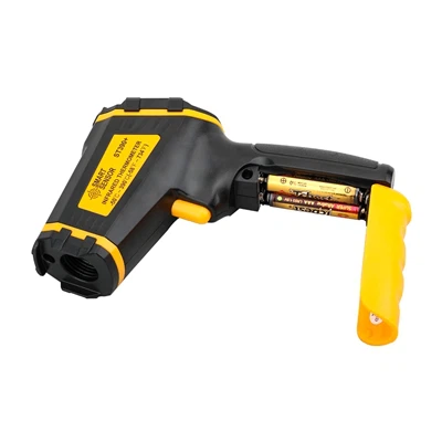
Digital illuminance meters are suitable for measuring light intensity in agricultural production, daily life, and outdoor travel. It uses a photoresistor as a photoelectric conversion device, which contains a DC power supply. The voltage conversion circuit, switch, photoresistor, testing circuit, A/D converter, decoder, display driver, and display are sequentially connected in series at the output terminal of the DC power supply. This utility model avoids the use of a photometric head, and only requires a 3V battery for the DC power supply. The decoder, display driver, and display are integrated on one integrated circuit card, making it simple in structure, small in size, easy to move, and has the advantages of sensitive response.
Structure principle of digital illuminance meter:
1. Introduction to Illuminance Testing
Illuminance is the surface density of the luminous flux received on the illuminated plane. Illuminometer is an instrument used to measure the illuminance on the illuminated surface and is one of the most commonly used instruments in illuminance measurement.
Instructions for using a digital illuminance meter:
1. Turn on the power.
2. Choose the appropriate measurement gear.
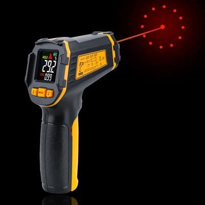
3. Open the light detection cover and align the front of the light detector with the desired light source.
4. Read the measured value on the illuminance meter display.
When reading the measurement value, if the highest digit displays "1", it indicates overload, and a higher gear should be immediately selected for measurement.
6. Data hold switch, turn the switch to "HOLD", the LCD displays the "□" symbol, and the display value is locked. Turn the switch to "NO" to cancel the reading lock function.
After the measurement work is completed, please cover the photodetector and turn the switch to "OFF" to turn off the instrument power.