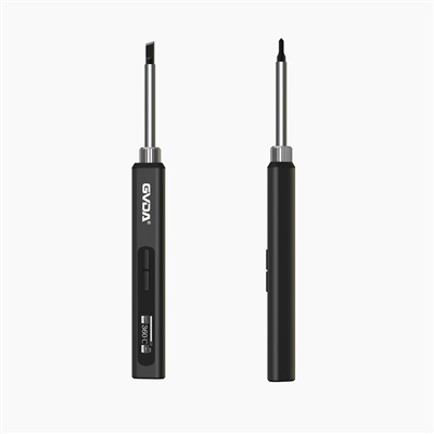
Test Analysis of Illuminance Meter Calibration Device
The space straightness error of the measurement axis of the photometer verification device, the standard filament plane and the perpendicularity error of the photometer photometer test surface relative to the measurement axis, these two shape and position errors have a direct impact on the accuracy of the photometer verification/calibration results. Among the results of the proficiency verification program of CNAS M0031 "Calibration of Indication Value of Illuminance Meter" organized by the China National Accreditation Service for Conformity Assessment and implemented and completed by the China Institute of Metrology from 2009 to 2010, a total of 86 calibration results were satisfactory. , 17 calibration results were unsatisfactory, accounting for 83.5% of satisfactory results, and 16.5% of unsatisfactory results. According to technical analysis, the primary cause of unsatisfactory calibration results is the inaccurate adjustment of the filament plane and the receiving surface of the optical head.
Our hospital has achieved a satisfactory result of En=0.00~0.23 in this proficiency verification of indication calibration (|En|<1.00, which means satisfaction). Based on the design and installation of photometer verification professionals and the experience of verifying/calibrating photometers, this paper analyzes the effects of these two methods of shape and position error detection and adjustment on ensuring the accuracy of photometer verification/calibration results.
Analyze and adjust the straightness error of the measurement axis space of the photometer verification device.
The light track of the photometer verification device is two parallel hollow round tubes, each hollow round tube includes 6 sections, each section is 1m long, and the head and tail of each hollow round tube are fastened to the V-shaped groove of the base. The unavoidable height difference in the Z direction and the offset difference in the X direction generated by the connection between the hollow circular tubes of each section, the diameter difference of the hollow circular tubes in each section, and the deflection caused by the self-weight combine to produce the straightness error of the optical track.
During the experimental verification of the light meter, the trolley installed with the luminous intensity standard lamp (referred to as the standard lamp) and its adjustment device moves to each verification point on the light track. The line connecting the center point of the standard lamp movement and the center point of the optical head of the tested light meter constitutes the measurement axis, which is a space connection line, and the degree of deviation from the center line is the measurement axis space straightness error. The straightness error of the measurement axis space is based on the straightness error of the light track, the deflection of the light track caused by the weight of the trolley is added, whether the center installation of the standard lamp and the photometric head is stable and reliable, whether the movement and positioning of the trolley are accurate and stable, etc. In general, it is more comprehensive and practical than the straightness error of the light track surface to affect the accuracy of the verification results of the light meter. Therefore, the method of measuring the straightness of the light track cannot be used to detect the spatial degree of the measurement axis, and the detection should be carried out on the straight line of the measurement space formed by the connection line between the center points of the standard lamp movement and the photometric center point.
First, adjust the surface of the first section of the light track to the level, install and fix a fixed trolley at one end (in the actual verification, the photometric head of the illuminometer to be inspected is installed on the trolley), place the autocollimator on the fixed trolley and adjust Its optical axis is located in the symmetrical middle of the optical track (two hollow circular tubes). Then place another movable trolley (standard light is installed on the trolley in the actual verification) at a position closer to the autocollimator, and place the reflector of the autocollimator on the trolley. Using the autocollimator pitch method to detect, obtain the measurement axis diagram composed of the center point of the optical head and the center points of the standard lamp movement, analyze the measurement axis diagram, and then adjust the Z direction and X direction of the measurement axis The spatial straightness error is as small as possible.