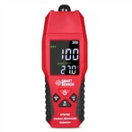
The method of using a multimeter to measure the continuity of a circuit.
1. Voltage Measurement Method
First, power on the control circuit. Set the range switch of the multimeter to the AC voltage range of 750V. Referring to the circuit schematic diagram, keep one probe of the multimeter on line 9, and use the other probe to measure lines 8, 7, 6, 5, 4, and 3 respectively. When the switch is not closed, the two probes are in - phase, and the voltage is 0V. When measuring lines 2 and 1, the two probes are out - of - phase, and the voltage is about 380V. This is the normal state of the circuit. If, during the measurement process, the voltage value at a certain point on a certain line does not match the circuit schematic diagram, in most cases, the point with the incorrect voltage value is the fault point!
2. Resistance Measurement Method
First, cut off the power to the circuit and test for the absence of electricity. After confirming that there is no electricity, set the range switch of the multimeter to the buzzer range or the resistance range. Place the two probes of the multimeter on line 1 and line 9 respectively.
Under normal circumstances, press the SB1 or SB2 button respectively, or directly manually press the springs of the two AC contactors (that is, manually close the normally - open contacts of KM1 or KM2). At this time, lines 1 and 9 are conductive, the circuit is connected, and the multimeter will show the corresponding resistance value of the coil.
If there is no resistance value, it means that the circuit is not connected. You need to measure and analyze the continuity of each point according to the circuit schematic diagram. The measurement method is similar to that of voltage measurement.
3.
The resistance measurement method and the voltage measurement method of the multimeter are the two most commonly used methods in circuit fault troubleshooting. It can be said that each has its own advantages and conveniences. The key is which one you are used to. Use the method you are most familiar with and measure with the help of the multimeter.
The continuity of a circuit can be roughly divided into two aspects: the power supply part and the electrical appliance part. To detect the power supply, set the measurement range of the multimeter to a voltage range higher than that of the circuit to be measured. For example, if the current power supply voltage is 220V AC, if you are using a pointer multimeter, set the range to AC 250V or AC 300V. If you are using a digital multimeter, you can set it to the AC 750V range. Then insert the black probe into the COM jack and the red probe into the VΩ jack. Although the requirement for polarity is not strict when measuring AC voltage, this is the requirement for using the instrument (https://www.dgzj.com/, Electrician's Home). Therefore, you should develop good working habits. If you are measuring for the first time, be sure to pay attention to safety. Hold the two probes in the same way as you hold chopsticks when eating, and stably insert them into the power socket, or the input or output terminal of the switch. At this time, the multimeter will display the current voltage. After measuring the voltage, if the power supply voltage is normal, the power supply part can be excluded. Otherwise, check the line between the socket and the distribution board switch, including the power switch of this circuit. Next, measure whether the electric griddle part is conductive. First, disconnect the electric griddle from the power supply. Set the multimeter to the 200Ω resistance range, and measure the power cord, power switch, temperature - control switch, and heating core of the electric griddle respectively. Except for the heating core of the electric griddle, the measurement result at this stage should be about 1Ω. Otherwise, there is a problem with that part and it should be dealt with.


