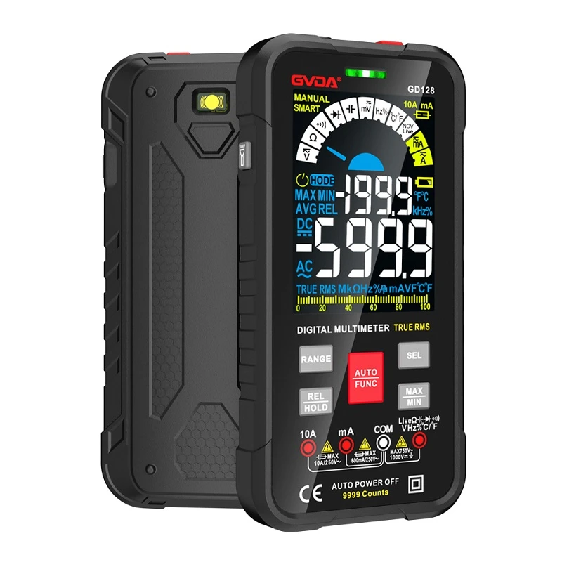
The multimeter measures current, voltage and resistance, which gear to adjust and how to read it.
First, observe and understand the structure of multimeter.
There are many kinds of multimeters with different shapes, but the basic structure and usage are the same.
The multimeter panel should have a meter head and a selector switch. There is also an ohm zero knob and a stylus jack. The following describes the role of each part:
(1) Header
The meter head of the multimeter is a sensitive galvanometer. The dial on the meter head is printed with various symbols, tick marks and numerical values. The symbol A-V-Ω indicates that this meter is a multimeter that can measure current, voltage and resistance. There are many scale lines printed on the dial, among which the right end marked with "Ω" is the resistance scale line, whose right end is zero and the left end is ∞, and the distribution of scale values is uneven. The symbol "-"or "DC" means DC, "~" or "AC" means AC, and "~" means the common scale line of AC and DC. A few lines of numbers under the scale line are scale values corresponding to different gears of the selector switch.
There is also a mechanical zero adjustment knob on the meter head to correct the pointer pointing to zero at the left end.
(2) Selector switch
The selector switch of multimeter is a multi-gear rotary switch. Used to select measurement items and ranges. General multimeter measurement items include: "MA"; DC current, "V": DC voltage, "V": AC voltage, "Ω": resistance. Each measurement item is divided into several different ranges for selection.
(3) stylus and stylus jack
The pens are divided into red and black. When using, the red stylus should be inserted into the jack marked with "+",and the black stylus should be inserted into the jack marked with "-".
Second, the use of multimeter
(a) multimeter before use, should do:
1. The multimeter is placed horizontally.
2. Check whether the hands stop at the zero position at the left end of the dial. If there is any deviation, you can gently turn the mechanical zero adjustment knob on the meter head with a small screwdriver to make the watch hand point to zero.
3. Insert the stylus into the stylus socket according to the above requirements.
4. Turn the selector switch to the corresponding item and range. You can use it.
(2) after the multimeter is used, it should be:
1. Pull out the stylus.
2. Turn the selector switch to the "OFF" position. If there is no such position, turn it to the maximum range of AC voltage, such as the "1000V" position.
3. If it is not used for a long time, the battery in the table should be taken out to prevent the battery electrolyte from leaking and corroding the internal circuit.
(1) Measuring DC voltage
The measuring steps are as follows:
1. Select the range. The DC voltage range of multimeter is marked with "V", and it has five measuring ranges: 2.5V, 10V, 50V, 250V and 500V. Select the measuring range according to the power supply voltage in the circuit. Because the power supply voltage in the circuit is only 3 volts, 10 volts is selected. If you don't know the voltage, you should first measure it with the highest voltage range and gradually switch to the low voltage range.
2. Measurement method. The multimeter should be connected in parallel with the circuit under test. The red pen should be connected to the junction of the tested circuit and the positive pole of the power supply, and the black pen should be connected to the junction of the tested circuit and the negative pole of the power supply.
3. Correct reading. Looking at the dial carefully, the scale line of the DC voltage file is the second scale line. When using the 10V file, the measured voltage value can be directly read by the third line of numbers below the scale line. Pay attention to the reading, the line of sight should be facing the pointer.