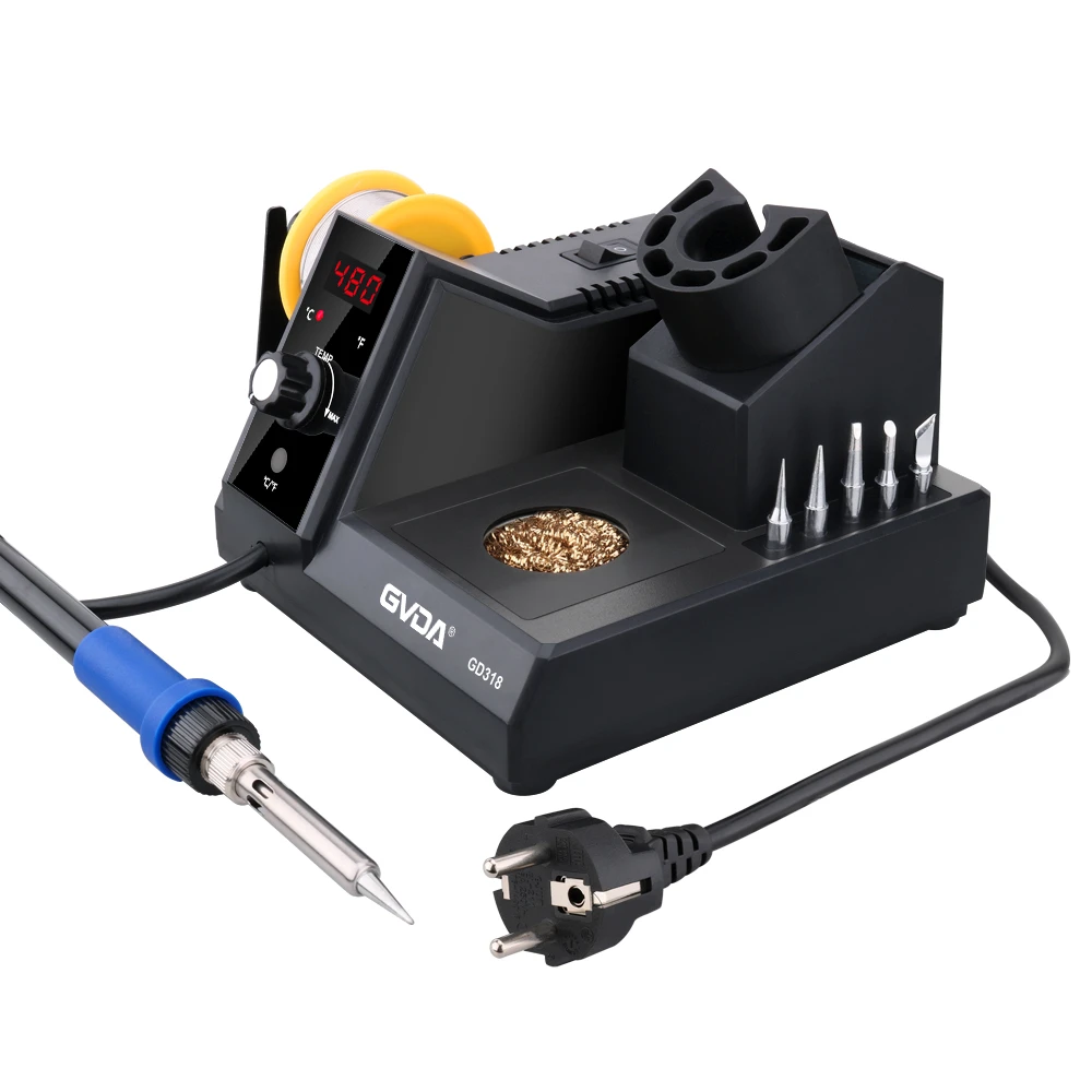
The soldering station should pay attention to the following four temperature zones during welding.
① Preheat zone (preheat zone). The purpose of preheating is twofold: one is to prevent one side of the printed board from being deformed by heat, and the other is to accelerate the melting of solder. For printed boards with larger areas, preheating is more important. Due to the limited heat resistance of the printed board itself, the higher the temperature, the shorter the heating time should be. Ordinary printed boards are safe below 150°C (not too long). Commonly used 1.5mm thick small-size printed boards can set the temperature at 150-160°C and the time is within 90 seconds. After the BGA device is unpacked, it should generally be used within 24 hours. If the package is opened too early, in order to prevent the device from being damaged during rework (popcorn effect), it should be dried before loading. The drying preheating temperature should be 100-110°C, and the preheating time should be longer.
②Medium temperature zone (soak zone). The preheating temperature at the bottom of the printed board can be the same as or slightly higher than the preheating temperature in the preheating zone. The temperature of the nozzle is higher than the temperature in the preheating zone and lower than that in the high temperature zone. The time is generally about 60 seconds.
③High temperature zone (peak zone). The temperature of the nozzle reaches its peak in this area. The temperature should be higher than the melting point of solder, but preferably not more than 200°C.
In addition to correctly selecting the heating temperature and time of each zone, attention should also be paid to the heating rate. Generally, when the temperature is below 100°C, the maximum heating rate does not exceed 6°C/s, and the maximum heating rate above 100°C does not exceed 3°C/s; in the cooling zone, the maximum cooling rate does not exceed 6°C/s.
(Ceramic-encapsulated BGA devices) and PBGA chips (plastic-encapsulated BGA devices) have certain differences in the above parameters: the solder ball diameter of CBGA devices should be about 15% larger than that of PBGA devices, and the composition of solder is 90Sn /10Pb, higher melting point. In this way, after the CBGA device is desoldered, the solder balls will not stick to the printed board.
The solder paste connecting the solder ball of the CBGA device to the printed board can use the same solder as the PBGA device (the composition is 63Sn/37Pb), so that after the BGA device is pulled out, the solder ball is still attached to the device pin and will not adhere to the printed board. board