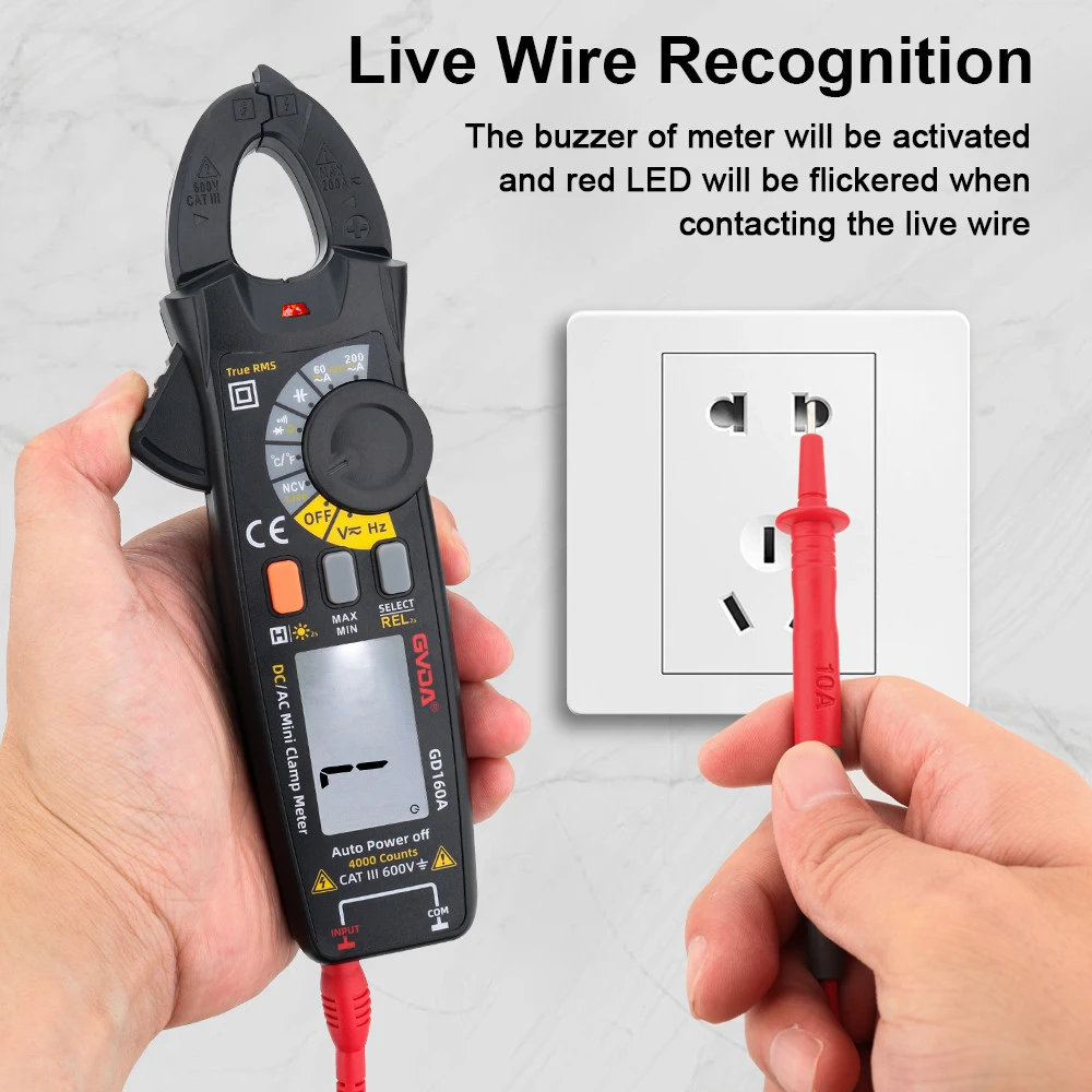
The specific operating steps of a digital clamp table
1. AC current measurement
① Turn the switch to the ACA1000A position.
② Keep the switch in a relaxed state.
③ Press the trigger to open the jaws and clamp one wire. If more than two wires are clamped, the measurement is invalid.
④ Read the numerical value. If the reading is less than 200A, turn the switch to the ACA200A position to improve accuracy. If it is not possible to read directly in the dark due to environmental conditions, press the hold button and take it to the bright spot to read.
2. Measurement of AC and DC voltage
① When measuring DC voltage, turn the switch to the ACA200A position. When measuring AC voltage, turn the switch to the ACV750V position.
② Keep the switch in a relaxed state.
③ Connect the red probe to the "V/Ω" end and the black probe to the "COM" end.
④ The red and black probes are connected in parallel to the tested circuit.
3. Resistance measurement
① Rotate the switch to the appropriate range of resistance.
② Keep the switch in a relaxed state.
③ Connect the red meter pen to the V/Ω terminal and the black meter rod to the COM terminal.
④ The red and black probes are connected to the two ends of the measured resistance Qiu. When measuring the online resistance, the circuit should be disconnected from the source, and the connection with the resistance should be discharged.
4. On/Off Test
① Turn the switch to 200n gear.
② The red and black pens are connected to the "V/Ω" and "COM" terminals respectively.
③ If the resistance between the red and black probes is less than (50 ± 25) Ω, the built-in buzzer will sound.
1. Clamp head 2. Clamp head trigger 3. Hold switch 4. Rotary switch 5. Display 6. Insulation test accessory interface 7. Common ground terminal 8. Voltage resistance input terminal 9. Handheld strap.
5. High resistance measurement
① Turn the switch to the "EXCERNALUNLT" 20M Ω or 2000M Ω position.
② The displayed value is unstable and in a free state.
③ Test the attachment by inserting three plugs into the three input sockets of the clamp meter.
④ The clamp meter switch and the test accessory range switch are both placed in the 2000M Ω position.
⑤ Test the input terminal of the accessory and connect it to the measured resistance;
⑥ Place the test attachment in the "ON" position, press the "PUSH" button, and the indicator light will light up. At this time, the display will show the measured value. If the reading is less than 19M Ω, select the 20M Ω range for the clamp meter test attachment to improve accuracy.shifting gears, clamp in the wires for measurement.
3. The voltage of the tested wire. The voltage level of the ground resistance clamp meter cannot be exceeded.
4. Poor insulation and wires are prohibited from being measured using a ground resistance clamp meter.
5. When measuring, pay attention to maintaining a safe distance from nearby charged objects. And attention should be paid not to cause phase to phase short circuits and phase to ground short circuits.
6. It is not suitable to measure circuit current in high temperature environments. It is not suitable to measure near strong magnetic fields, as external magnetic fields have a significant impact on the measurement values. Grounding resistance clamp meters should not be used for measurement near high load current equipment such as busbars, large capacity motors, and transformers. It should be measured in a different location to reduce error short circuits caused by magnetic fields.
7. Measurement should not be carried out in damp areas or thunderstorm weather, as the grounding resistance clamp meter must be held by hand for direct measurement of electrical equipment in operation. The jaws, handles, and hands of the measuring personnel of the grounding resistance clamp meter must be kept clean and dry during measurement.
8. The ground resistance clamp meter has a large error in measuring non rated current. The working principle of a ground resistance clamp meter determines that it is necessary to use a ground resistance clamp meter at the specified rated rate. In addition to measuring sine wave currents, measuring other waveform currents will result in errors. Generally, odd harmonic waves have larger waveform errors than even spectral waves. Especially when the error of the third harmonic becomes larger, using a ground resistance clamp meter to measure the half wave rectification current also results in a larger error.
9. After use, the gear should be set to the high current gear, and if there is a watch cover, it should be placed in the watch cover. Store in a dry, dust-free, non corrosive gas, and vibration free place.
10. High voltage current cannot be measured, and the voltage of the tested circuit cannot exceed the rated voltage of the ground resistance clamp meter. The grounding resistance clamp meter cannot measure high-voltage electrical equipment.
That is, the measured capacitance CX is directly proportional to the output voltage C0, thus achieving CX → V conversion. In order to match the basic capacitance level with the 2V level of the digital multimeter, the oscillation frequency of the Wentz oscillator is selected as 400Hz, the effective voltage value is 1V, R1 is taken as 20k Ω, and C1 is taken as 0.1 μ F. R2 varies from 200 Ω -2k Ω -20k Ω -200k Ω -200k Ω -2M Ω, corresponding to a measurement capacitance range of 20 μ F-2 μ F-200nF-20nF-2nF.
2. Measure small capacitance
The typical range of a three and a half digit multimeter for measuring capacitance is 2000pF to 20 μ F, and it is powerless to measure small capacitors below 1pF. According to the capacitive impedance method and using high-frequency signals, the measurement of small capacitors can be achieved. The measurement circuit diagram is shown in Figure 2. CX is the measured capacitance, and Rf is the feedback resistance of the reverse phase terminal. When the input frequency of a sine signal Vi is f, the impedance presented on CX and the gain of the operational amplifier are: when A and Rf are constant, the frequency of the sine signal f is inversely proportional to the measured capacitance CX. To measure smaller capacitance, use high-frequency signals for measurement.