Tool Measuring Microscope STM6 Adjustment Methods
The debugging of tool microscope STM6, from the application point of view, mainly includes the horizontal adjustment of the carrier stage, the vibration-proof adjustment of the working table, the horizontal adjustment of the eyepiece metre line, the horizontal adjustment of the video system and the precision correction, etc., which will be summarized below:
1, the level of the carrier platform adjustment: according to the level placed on the carrier platform to determine the level of the carrier platform installation, such as the need to adjust the actual situation can be adjusted according to the three support feet, until the level of the bubble in the ruler stays in the ruler near the centre can be.
2, anti-vibration adjustment of the worktable: machine start-up if you find that the data display data is not stable, you can judge that the worktable is not stable enough, you can increase the worktable anti-vibration pads, replacement of a more solid worktable to complete.
3, the eyepiece Meter line level adjustment: in the focusing clear eyepiece field of view to find an eye-catching dot, move it to one end of the eyepiece Meter line (X, Y direction can be, here to the X direction for the force) and rely on the X-direction, shake the X-direction handle, so that the small point of the X-direction along the line to move to the other end of the engraved, if the point of the small point away from the X-direction of the line, that is, the eyepiece to the corresponding direction of the adjustments to make the small point close to the X-direction of the line. If the dot deviates from the X-direction drawing line, adjust the eyepiece in the corresponding direction so that the dot is close to the X-direction drawing line, and repeat the adjustment in this way until the dot is able to stay on the X-direction drawing line when the carrier is moving along the X direction.
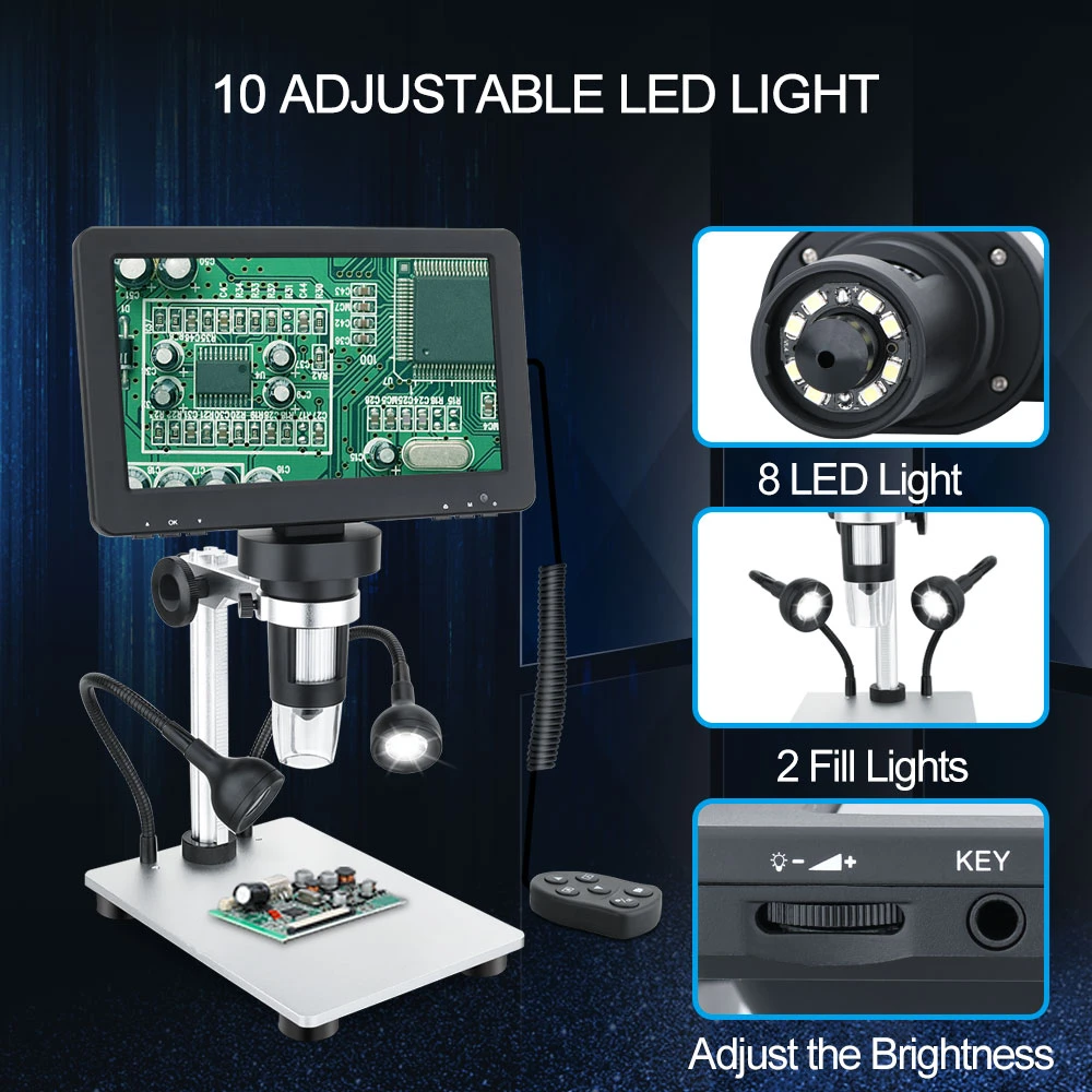
4, the level of the video system adjustment: (this project generally do not need to adjust, unless the microscope is equipped with a rotary stage and the user needs to adjust the level of the components through the frequency adjustment system) take the standard block gauge placed on the rotary stage, the use of adjusted eyepieces m line to adjust the whole block to the level; will be the CCD (video system) and the video interface screwed tightly and then connect the interface to the microscope and lock; move the end of the block gauge leaning towards the software Move one end of the block gauge to the end of the X-direction engraved line of the crosshair in the window, shake the X-axis handle to make the software field of view to the other end of the block gauge, at this time, if the fast gauge deviates from the X-axis, rotate the CCD so that the block gauge is close to the X-axis (this adjustment is the same as that of the eyepiece). So repeatedly adjusted until the block gauge always move in the X direction, at this time the physical coordinate system of the CCD can be considered parallel to the mechanical coordinate system of the microscope stage.