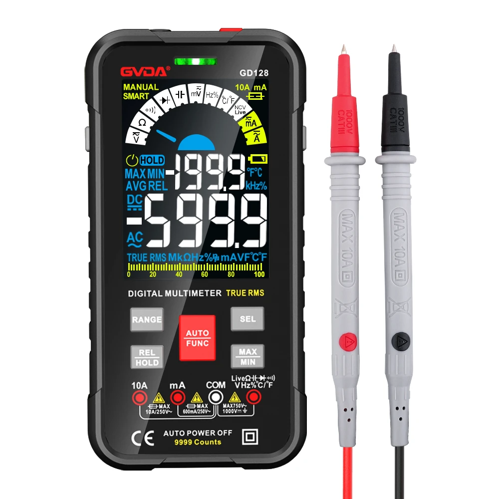
Use a multimeter to judge the quality of 14 common circuit components
In the maintenance process, a multimeter should be used to detect the quality of electronic components according to the fault conditions. If the measurement method is incorrect, it is likely to lead to misjudgment, which will cause difficulties in maintenance work and even cause unnecessary economic losses. The measurement method is divided into two methods: component test and circuit board in-circuit test. On-road test: disconnect the power supply of the inverter, and measure the components on the circuit board without dismantling the components on the circuit board. For component breakdown, short-circuit, and open-circuit faults, this detection method can easily and quickly find damaged components, but the influence of the components measured on the circuit board and their parallel components on the measurement results should also be considered , so as to avoid misjudgment errors. The following are the methods for judging the quality of nine components:
1. Detection of ordinary diodes
Measure with MF47 type multimeter, connect the red and black test leads to the two ends of the diode respectively, read the readings, and then exchange the test leads to measure. Judging from the results of the two measurements, the forward resistance of low-power germanium diodes is usually 300-500Ω, and that of silicon diodes is about 1kΩ or more. The reverse resistance of the germanium tube is tens of thousands of ohms, and the reverse resistance of the silicon tube is more than 500kΩ (the value of the high-power diode is much smaller). A good diode has a lower forward resistance, a larger reverse resistance, and the larger the difference between the forward and reverse resistances, the better. If the measured forward and reverse resistances are small and close to zero, it means that the diode is short-circuited inside; if the forward and reverse resistances are large or tend to be infinite, it means that the inside of the tube is broken. In both cases the diode needs to be scrapped.
On the road test: test the forward and reverse resistance of the diode PN junction, it is easier to judge whether the diode is a breakdown short circuit or an open circuit.
Two, triode detection
Turn the digital multimeter to the diode gear, and measure the PN junction with a test lead. If the forward direction is turned on, the displayed number is the forward voltage drop of the PN junction.
First determine the collector and the emitter; measure the forward voltage drop of the two PN junctions with a test lead, the emitter e is the one with the larger voltage drop, and the collector c is the smaller one. When testing two junctions, if the red test lead is connected to the common pole, the tested transistor is NPN type, and the red test lead is connected to the base b; if the black test lead is connected to the common pole, the tested transistor is PNP type, And this is extremely base b. After the triode is damaged, the PN junction has two situations: breakdown short circuit and open circuit.
On-the-road test: The on-road test of the triode actually determines whether the triode is damaged by testing the forward and reverse resistances of the PN junction. The branch resistance is greater than the forward resistance of the PN junction, and the forward and reverse resistances measured in normal conditions should be significantly different, otherwise the PN junction will be damaged. When the branch circuit resistance is less than the forward resistance of the PN junction, the branch circuit should be disconnected, otherwise the quality of the triode cannot be judged.
3. Three-phase rectifier bridge module detection
Take the SEMIKRON (Siemens) rectifier bridge module as an example, as shown in the attached figure. Turn the digital multimeter to the diode test gear, connect the black test lead to COM, the red test lead to VΩ, and use the red and black test leads to measure the forward and reverse diode characteristics between phases 3, 4, and 5 and poles 2 and 1 to check and judge. Whether the rectifier bridge is in good condition. The greater the difference between the measured forward and reverse characteristics, the better; if the forward and reverse directions are zero, it means that the detected phase has been broken down and short-circuited; if the forward and reverse directions are both infinite, it means that the detected phase has been broken. As long as one phase of the rectifier bridge module is damaged, it should be replaced. Source: Transmission and Distribution Equipment Network
Fourth, the experience of MOS tube quality
(1) Connect the black test lead to the D pole and the red test lead to the S pole, generally with a resistance value of 500-600
(2) On the premise that the black test pen does not move, tap the G pole with the red test pen, and then use the red pen to measure the S pole, there will be continuity
(3) The red test lead is connected to the D pole, and the black test lead is below the G pole and then connected to the S pole. The measured resistance value is the same as that measured by 1, indicating that the MOS tube is working normally~~
The following methods are summarized in the maintenance process. On the board, without the CPU, directly hit the resistance value of S and G. If it is less than 30 ohms, it is basically broken. You can compare the above.
The method of measuring MOS tube with digital multimeter: (use 2-pole tube file) method to remove the bad tube and measure.
Five, inverter IGBT module detection
Turn the digital multimeter to the diode test gear, and test the forward and reverse diode characteristics between C1.E1 and C2.E2 of the IGBT module and between the gate G and E1 and E2 to judge whether the IGBT module is in good condition.
Take the German eupec25A/1200V six-phase IGBT module as an example (refer to the attached picture). Remove the wires of the U, V, W phases on the load side, use the diode test gear, connect the red test lead to P (collector C1), and the black test lead to measure U, V, W (emitter E1) in turn, the multimeter shows the maximum value; The test leads are reversed, the black test lead is connected to P, the red test lead is used to measure U, V, and W, and the multimeter shows a value of about 400. Then connect the red test lead to N (emitter E2), the black test lead to measure U, V, W, and the multimeter displays a value of about 400; the black test lead is connected to N, the red test lead measures U, V, W (collector C2), and the multimeter displays the value to the maximum. The forward and reverse characteristics of each phase should be the same. If there is a difference, it means that the performance of the IGBT module has deteriorated and should be replaced. When the IGBT module is damaged, only the breakdown short circuit occurs.
The red and black test pens measure the forward and reverse characteristics between the gate G and the emitter E respectively. The values measured by the multimeter twice are the maximum. At this time, it can be determined that the gate of the IGBT module is normal. If there is a value displayed, the gate performance has deteriorated and this module should be replaced. When the forward and reverse test results are zero, it means that the detected one-phase gate has been broken down and short-circuited. When the gate is damaged, the Zener tube that protects the gate of the circuit board will also be broken down and damaged.
6. Detection of electrolytic capacitors
When measuring with the MF47 type multimeter, the appropriate range of the multimeter should be selected for the electrolytic capacitors of different capacities. According to experience, in general, electrolytic capacitors below 47μF can be measured in R×1K range, and electrolytic capacitors larger than 47μF can be measured in R×100 range.
Connect the red test lead of the multimeter to the negative electrode of the capacitor, and the black test lead to the positive electrode. At the moment of first contact, the pointer of the multimeter deflects to the right by a large amount, and then gradually turns to the left until it stops at a certain position (returns to the infinity position). The resistance value at this time is the forward leakage resistance of the electrolytic capacitor. The larger the value, the smaller the leakage current and the better the capacitor performance. Then, swap the red and black test pens, and the multimeter pointer will repeat the above-mentioned swing phenomenon. However, the resistance measured at this time is the reverse leakage resistance of the electrolytic capacitor, which is slightly smaller than the forward leakage resistance. That is, the reverse leakage current is larger than the forward leakage current. Practical experience shows that the leakage resistance of electrolytic capacitors should generally be above several hundred thousand ohms, otherwise it will not work properly.
In the test, if there is no charging phenomenon in the forward and reverse phases, that is, the needle does not move, it means that the capacitance of the capacitor has disappeared or the internal short circuit; Can no longer be used.
On-the-road test: On-the-road testing of electrolytic capacitors should only be used to check for serious leakage or breakdown faults, and the accuracy of testing minor leakage or small-capacity electrolytic capacitors is poor. In the road test, the influence of other components on the test should also be considered, otherwise the read value will be inaccurate, which will affect the normal judgment. Electrolytic capacitors can also use a capacitance meter to detect the capacitance value between the two ends to judge the quality of electrolytic capacitors.
7. Simple testing of inductors and transformers
(1) Inductor test
Use the MF47 multimeter to test the resistance of the inductor. If the resistance value of the tested inductor is zero, it means that the internal winding of the inductor has a short circuit fault. Note that the multimeter must be zeroed during operation, and the test should be repeated several times. If the resistance value of the tested inductor is infinite, it means that an open circuit fault has occurred at the winding or the lead-out pin of the inductor and the contact of the winding.
Source: Transmission and Distribution Equipment Network
(2) Simple test of transformer
Insulation performance test: Use the multimeter resistance gear R×10K to measure the resistance values between the iron core and the primary winding, the primary winding and the secondary winding, and the iron core and the secondary winding, which should be infinite. Otherwise, the insulation performance of the transformer is poor.
Measure the winding on-off: Use the multimeter R×1 gear to measure the resistance between the primary and secondary windings of the transformer. Generally, the resistance of the primary winding should be tens of ohms to hundreds of ohms. The smaller the transformer power, the greater the resistance value; The resistance value of the secondary winding is generally several ohms to several hundred ohms. If the resistance value of a group is infinite, the group has an open circuit fault.
Note: This measurement method is only a rough estimate, and some transformers with a slight short-circuit between the turns of the windings are inaccurate.
8. Simple test of resistance value of resistor
When measuring resistance on the road, the power supply of the circuit board should be cut off, and the influence of other components in the circuit on the resistance value should be considered. If a capacitor is connected to the circuit, the capacitor must also be discharged. The multimeter needle should point to the center of the scale for accurate readings.
9. SMD components
(1) Types of SMD components
Inverter electronic circuit boards now mostly use chip components, also known as surface mount components, which are micro-miniature electronic components with no leads or short leads that are suitable for surface mounts. There are many varieties and specifications of SMD components, which can be divided into rectangular, cylindrical and special-shaped structures according to shape. According to the type, it can be divided into chip resistors, chip capacitors, chip inductors, chip semiconductor devices (can be divided into chip diodes and chip transistors), and chip integrated circuits. Source: Transmission and Distribution Equipment Network
(2) Demolition and soldering of SMD components
Use a 35W internal heating electric soldering iron with a long-life oxidation-resistant tip. Wipe off the sticky residue from the tip of the soldering iron, leaving only a thin layer of solder. The disassembly and welding operations of the SMD components of the devices at both ends are relatively easy. SMD integrated circuits have thin and many pins, small pin spacing, compact arrangement of surrounding components, and difficult disassembly and assembly. Their disassembly and welding are difficult without special tools. Here we focus on the disassembly and welding operations of SMD integrated circuits.
(3) Disassembly method
If it has been judged that the integrated circuit block is damaged, use a paper cutter to cut off the pins at the root and remove the integrated circuit block. Be careful not to cut the cutter head to the circuit board when cutting. Then, clamp the broken feet with tweezers, use a pointed soldering iron to melt the solder on the broken feet, and remove the broken feet one by one.
(4) Welding method
Before soldering, use alcohol to clean up the excess solder and dirt on the copper piers of the circuit board from which the integrated circuit block was removed, coat the pins of the integrated circuit block with alcohol rosin, and coat the pins with a thin layer of tin. . Then, check the position of the pins of the integrated circuit, place the integrated circuit block on the circuit board to be soldered, lightly press the integrated circuit block, and use an electric soldering iron to solder the pins on the four corners of the integrated circuit block to fix the integrated circuit block. OK, and then solder the other pins one by one. In order to ensure the welding quality, it is better to use thinner solder wire, such as 0.6mm solder wire, for better welding effect.