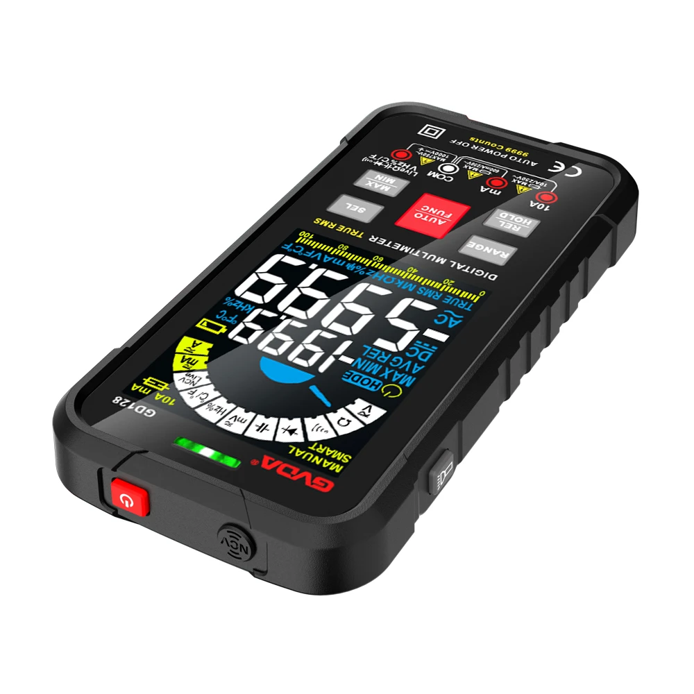
Common fault inspection and maintenance skills of digital multimeter
For a faulty instrument, we should first check and judge whether the fault phenomenon is common (all functions cannot be measured) or individual (individual functions or individual ranges), and then distinguish the situation and solve the problem.
1. If all gears fail to work, check the power supply circuit and A/D converter circuit. When checking the power supply part, you can remove the laminated battery, press the power switch, connect the negative power supply of the meter to be tested with the positive stylus, and connect the negative stylus to the positive power supply (for the digital multimeter), and switch to the diode measurement file. If the diode direct voltage is displayed, it means that the power supply part is good; if the deviation is large, it means that there is something wrong with the power supply part. If there is an open circuit, focus on checking the power switch and battery leads. If there is a short circuit, it is necessary to use the open circuit method to gradually disconnect the components that use the power supply, focusing on checking the operational amplifier, timer and A/D converter. If a short circuit occurs, it usually damages more than one integrated component. Check the A/D converter at the same time as the basic meter, which is equivalent to the DC meter of the analog multimeter. The specific inspection method is as follows:
(1) The range of the meter under test is turned to the lowest DC voltage;
(2) Measure whether the working voltage of A/D converter is normal. According to the model of A/D converter used in the table, corresponding to V+ pin and COM pin, whether the measured value is consistent with its typical value.
(3) Measure the reference voltage of A/D converter. At present, the reference voltage of commonly used digital multimeter is generally 100mV or 1V, that is, measure the DC voltage between VREF+ and COM. If it deviates from 100mV or 1V, it can be adjusted by an external potentiometer.
(4) Check the display number with zero input, and short-circuit the positive terminal IN+ and the negative terminal IN- of the A/D converter to make the input voltage Vin=0, and the instrument displays "00.0" or "00.00".
(5) Check the full bright strokes of the display. Short-circuit the TEST pin of the test terminal with the positive power supply terminal V+, so that the logic ground becomes high potential, and all digital circuits stop working. Because DC voltage is applied to each stroke, the alignment table of all strokes shows "1888" and the alignment table shows "18888". If there is a lack of strokes, check whether there is poor contact and disconnection between the corresponding output pin of A/D converter and conductive adhesive (or wire) and the display.
2. If there is something wrong with individual files, it means that the A/D converter and the power supply are working normally. Because the DC voltage and the resistor share a set of voltage dividing resistors; AC/DC current sharing shunt; Ac voltage and AC current share a set of AC/DC converter; Others, such as Cx, HFE and F, are composed of independent converters. Understand the relationship between them, and then according to the power diagram, it is easy to find the fault location. If the measured small signal is inaccurate or the displayed digital jitter is large, it is important to check whether the contact of the range switch is good.
3. If the measured data is unstable, and the value always increases cumulatively, and the input end of A/D converter is shorted, and the displayed data is not zero, it is generally caused by the poor performance of the reference capacitor of 0.1 μ f..
According to the above analysis, the basic repair sequence of digital multimeter should be: digital meter head → DC voltage → DC current → AC voltage → AC current → resistance gear (including buzzer and check diode positive pressure drop) →Cx→HFE, F, H, T, etc. But it should not be too mechanical. Some obvious problems can be dealt with first. However, the above procedures must be followed when making adjustments.
In short, a faulty multimeter, after proper testing, should first analyze the possible parts of the fault, and then find the fault position according to the circuit diagram for replacement and repair. Because the digital multimeter is a relatively precise instrument, components with the same parameters must be used to replace components, especially the A/D converter, and the integrated block that has been strictly screened by the manufacturer must be used, otherwise there will be errors and the required accuracy will not be achieved. The newly replaced A/D converter also needs to be checked according to the method mentioned above, and it must not be believed because it is new.
At present, there are many manufacturers of digital multimeters in China, and the quality is also good and bad. The quality problem of double-sided copper clad plate is not easy to find in repair. When the insulation strength of resin plate is not enough, it is mainly manifested in the large error when measuring high voltage, which should be distinguished from the resistance change of voltage divider when repairing. In this case, it is best to use the open circuit method to find the fault point. The burnt and carbonized parts shall be cleaned to meet the insulation requirements. When the signal cannot be input due to the fracture of the transition hole of the double-sided connection line, it is easy to be confused with the bad change-over switch and difficult to separate. This kind of fault should be found by short circuit method.