Error Analysis of Measuring Line Tower Grounding Resistance by Clamp Meter
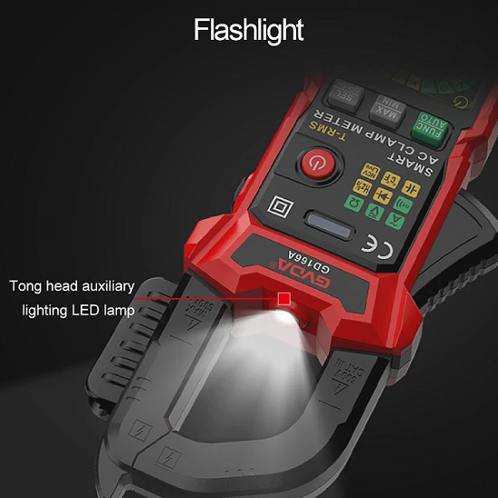
Grounding resistance measurement is a necessary means to check whether the grounding device meets the requirements of the regulations. The traditional method of measuring the grounding resistance of transmission line poles and towers generally adopts the grounding meter method, which needs to arrange electrode leads of more than tens of meters on site, and the workload is very heavy. The clamp meter method is a new method that has appeared in recent years. It does not need current, voltage poles and external power supply, and does not need to disconnect the ground connection, as long as the clamp meter clamps the ground wire of the tower. The clamp meter method generally uses different frequency measurements. Since the loop resistance is measured by the clamp meter method, in addition to the grounding resistance of the grounding body, it can also be found that the loop resistance of the entire grounding loop increases due to weather, soil, or some grounding rod corrosion or poor contact, and then The latter cannot be found through the traditional grounding shaker, because the corrosion or poor contact does not necessarily exist on the grounding body in the soil, but may also exist in the down conductor and other positions. Since the clamp meter method measures the different frequency (or high frequency) loop resistance, it cannot simply be considered as the power frequency grounding resistance. Measure the error characteristics of grounding resistance.
1. Calculation of errors in grounding resistance of line poles and towers measured by clamp meter method
The simplified layout diagram of the clamp meter measurement method is shown in Figure 1, where R; is the grounding resistance of the measured tower, and Ri ~ Rn is the grounding resistance of the tower connected afterwards. When the lightning protection line of the transmission line is directly connected to the ground of the iron tower, the
All towers form a parallel network through lightning protection lines, and each tower is a branch. Assume that the parallel connection value of the grounding resistance of other branches except R is Ro. When n is large, Ro < R. There are two coils of current and voltage in the grounding resistance clamp meter currently available in the market, and the former provides different frequency test power supply U like a transformer. , U forms a current I in the closed test loop, and I is measured again by another coil in the clamp meter, namely the voltage coil. The instrument can calculate the loop resistance R by obtaining the value of the power supply potential ∪ and the measured current I. Since Ro<Rj, so R≈Rj, the value displayed by the clamp meter is approximately considered as the tower grounding resistance Rjo.
Obviously, there is a measurement method error between the loop resistance R and the grounding resistance RJ of the tower, or the loop impedance (resistance) increases. Taking the head-end tower as an example, the increase includes the measured head-end tower reactance Xg, the lightning conductor impedance Z (= R + jX) of the current file and the sum of the parallel impedances of all subsequent towers from No. 2 to No. n.
For different number of towers, different heights of towers, forms of lightning conductors and different grounding resistances, the increase of loop impedance is not the same. Obviously, the larger n is, the parallel impedance of all subsequent towers No. 2 to No. n will converge to a minimum value. The basic tower reactance Xg and the lightning conductor impedance Z of this file constitute the basic loop impedance increase, that is, the series impedance part of the loop.