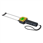
The role of clamp ammeter_ reading of clamp ammeter
The role of the clamp meter
A clamp ammeter is a combination of a current transformer and an ammeter. The iron core of the current transformer can be opened when the wrench is squeezed; the wire through which the measured current passes can pass through the iron core. The measured circuit wire becomes the primary coil of the current transformer, and the current is induced in the secondary coil current.
Usually, when measuring the current with an ordinary ammeter, it is necessary to cut off the circuit and shut down the circuit before connecting the ammeter for measurement. This is very troublesome, and sometimes the motor in normal operation does not allow this. At this time, it is much more convenient to use a clamp ammeter, which can measure the current without cutting off the circuit.
The clamp meter can be changed to different ranges by changing the gear of the switch. But it is not allowed to operate with electricity when shifting gears. The clamp meter is generally not high in accuracy, usually 2.5 to 5 grades. For the convenience of use, there are switches of different ranges in the meter for the function of measuring different levels of current and measuring voltage.
Clamp meters were originally used to measure alternating current. , but now the multimeter also has some functions, which can measure AC and DC voltage, current, capacitance, diode, triode, resistance, temperature, frequency and so on.
The clamp ammeter can measure the photovoltaic DC current and the output AC current of the inverter. Special attention should be paid to: some clamp ammeters do not have a DC function, and the jaws must be closed tightly, and the range cannot be changed with power on.
Clamp meter reading
1. Select gear and range. Turn the meter switch to the DC current "mA" position, and select the correct range according to the measured current. If the current is not known, in order to prevent the current from being too large and exceeding the range, you can first place the DC current at the highest gear for testing. If the range is too large, then reduce the range until the range is appropriate.
2. Connect the circuit in series. When the multimeter measures current, the test leads must be connected to the current in series, and the red test lead is connected to the high potential end of the circuit, and the black test lead is connected to the low potential end of the current.
3. Reading method:
(1) Correctly select the scale line for reading.
(2) Converted current value: Current value = the number of scales pointed by the pointer × the size of the range / the maximum value of the selected scale.


