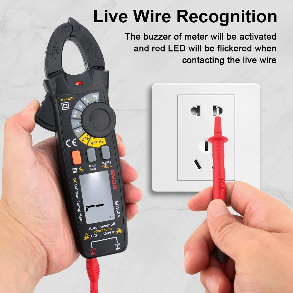
Common usage methods and solutions for digital clamp watches
AC current measurement
① Turn the switch to the ACA1000A position.
② Keep the switch in a relaxed state.
③ Press the trigger to open the jaws and clamp one wire. If more than two wires are clamped, the measurement is invalid.
④ Read the numerical value. If the reading is less than 200A, turn the switch to the ACA200A position to improve accuracy. If it is not possible to read directly in the dark due to environmental conditions, press the hold button and take it to the bright spot to read.
Measurement of AC and DC voltage
① When measuring DC voltage, turn the switch to the ACA200A position. When measuring AC voltage, turn the switch to the ACV750V position.
② Keep the switch in a relaxed state.
③ Connect the red probe to the "V/Ω" end and the black probe to the "COM" end.
④ The red and black probes are connected in parallel to the tested circuit.
Resistance measurement
① Rotate the switch to the appropriate range of resistance.
② Keep the switch in a relaxed state.
③ Connect the red meter pen to the V/Ω terminal and the black meter rod to the COM terminal.
④ The red and black probes are connected to the two ends of the measured resistance Qiu. When measuring the online resistance, the circuit should be disconnected from the source, and the connection with the resistance should be discharged.
On/Off Test
① Turn the switch to 200n gear.
② The red and black pens are connected to the "V/Ω" and "COM" terminals respectively.
③ If the resistance between the red and black probes is less than (50 ± 25) Ω, the built-in buzzer will sound.
1. Clamp head 2. Clamp head trigger 3. Hold switch 4. Rotary switch 5. Display 6. Insulation test accessory interface 7. Common ground terminal 8. Voltage resistance input terminal 9. Handheld strap.
High resistance measurement
① Turn the switch to the "EXCERNALUNLT" 20M Ω or 2000M Ω position.
② The displayed value is unstable and in a free state.
③ Test the attachment by inserting three plugs into the three input sockets of the clamp meter.
④ The clamp meter switch and the test accessory range switch are both placed in the 2000M Ω position.
⑤ Test the input terminal of the accessory and connect it to the measured resistance;
⑥ Place the test attachment in the "ON" position, press the "PUSH" button, and the indicator light will light up. At this time, the display will show the measured value. If the reading is less than 19M Ω, select the 20M Ω range for the clamp meter test attachment to improve accuracy.stability and precision, supporting lower ohmic and current ranges than a typical 6-and-a-half-digit digital multimeter. In addition, this also gives us a competitive measurement advantage over our main competitor, the Agilent 34980A. Please refer to Table 1 for the main features and advantages of a digital multimeter.
An important application of the 3706 host is to use it in conjunction with the 2600 series digital source meters (in many cases, multiple digital source meters are used), which requires a simple and low-cost benchmark standard to check and verify each source measurement unit. The digital multimeter in the 3706 host can provide this capability.
The system advantages of having a benchmark level 7-and-a-half-digit multimeter include:
High stability and precision, used for calibrating and monitoring other support system equipment and instruments,
High sensitivity Ohm test for preventive monitoring of relays and interconnect devices,
All of this is priced lower than a typical 6-and-a-half-digit multimeter!