Concrete operation steps of digital clamp meter
1. Measurement of AC current
Switch to the ACA1000A gear.
2Maintain the switch's relaxed position.
To open the jaws and clamp one wire, pull the trigger. The measurement will be deemed invalid if more than two wires are clamped.
4 Check the result. To increase accuracy, set the switch to ACA200A if the reading is less than 200A. Press the hold button and read it in a bright area if reading directly in the dark is not possible due to the environment.
2. Measuring AC and DC voltage
1 Set the switch to ACA200A for measuring DC voltage and ACV750V for monitoring AC voltage.
2Maintain the switch's relaxed position.
3Assemble the test leads by connecting the black test lead to the "COM" terminal and the red test lead to the "V/" terminal.
4The black and red test leads are attached in parallel to the circuit being checked.
3. Resistance analysis
1 Turn the switch to the appropriate range of the electric barrier.
2Maintain the switch's relaxed position.
3Connect the black test lead to the "COM" terminal and the red test lead to the "V/" terminal.
4The two ends of the measured resistance are connected to the appropriate red and black test leads. Lines from the neutral source and the one connecting to the resistance should be drained prior to measuring the online resistance.
Test of continuity
1 Set the dial to 200n.
2The "V/ terminal" and "COM" terminals are linked, respectively, to the red and black test leads.
3The built-in buzzer will ring if the resistance between the red and black test leads is less than (5025).
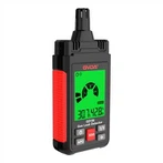
two clamp heads and a trigger three-hold switch Four-rotor switch 5-Display 6-Accessory interface for insulation testing Common ground terminal: seven 9-Hand strap 8-Voltage resistance input terminal
5. Measurement of high resistance
The switch should be set to "EXTERNALUNLT" 20M or 2000M.
2The value is displayed in an unstable and unconstrained condition.
3 Connect the three connectors from the test accessories to the clamp meter's three input jacks.
4The test accessory's range switch, clamp meter switch, and range switch are all set to 2000M.
5 The measured resistance is wired to the test accessory's input terminal;
⑥ Once the test accessory is in the "ON" position and the "PUSH" button is pressed, the indicator light turns on and the measured value is displayed on the display. To increase accuracy, the clamp meter test accessory's range should be set to 20M if the reading is less than 19M. Spend.