Digital multimeter diode gear and diode measurement method
Diode gear is a high frequency of use of a gear, generally in the digital meter have this gear, the logo is a diode symbol, there may be a similar "signal" around the symbol, you can refer to the above picture of the representation.
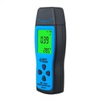
Rotate the multimeter to this gear, see if the display shows the above mentioned "signal" symbol, in fact, this is the buzzer file, if the red and black pens shorted, you will hear the buzzer sound, with this gear can measure the conductor's on and off, but today we are talking about another, press the switch button on the digital table! , you can see a diode symbol shown on the display.
As the red pen of the digital meter connected to the positive terminal of the internal power supply, the black pen connected to the negative terminal of the internal power supply, so the digital meter to measure the diode when the red pen on the diode's positive terminal, the black pen is connected to the negative terminal of the diode, the normal display will show the diode's positive conduction voltage drop, for example, the following figure of the diode conduction voltage drop of 0.607 volts.
For a normal diode can be measured on the voltage drop, but the diode is reversed (red pen connected to the diode's negative, black pen connected to the diode positive) is not measured any results, so this method can also determine the diode's good or bad, you can refer to the results of the measurement in the figure below.
Measurement of diodes is to ordinary rectifier tube as an example, in fact, for other types of diodes can also be basically used in this way, for example, with this gear can also be measured out of the LED lights (light-emitting diodes) conduction voltage drop.