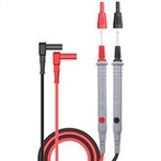
Digital multimeter test electrolytic capacitor
(1) Direct detection with capacitance files
Some digital multimeters have the function of measuring capacitance, and the range of UT51 is divided into two levels: 200μ and 20μ.
When measuring, first connect the red test lead to the current terminal hole, the black test lead to the COM terminal hole, select the capacitor gear for the function gear, and then use the red and black test leads to connect the two pins of the discharged capacitor (note the polarity), and select the appropriate The displayed data can be read after measuring.
The 200μ file is suitable for measuring capacitance between 20uF and 200μF; the 20μ file is suitable for measuring capacitance between 2μF and 20μF.
(2) Preliminarily judge whether the capacitor is good or not with the buzzer
The quality of electrolytic capacitors can be checked at high speed by using the buzzer gear of the digital multimeter. Turn the digital multimeter to the buzzer position, and use two test leads to distinguish the contact with the two pins of the capacitor Cx under test. Then, measure again by exchanging the two test leads, and the buzzer should sound, which indicates that the electrolytic capacitor under test is basically normal. At this time, you can dial to the 20MΩ or 200MΩ high-resistance file to measure the leakage resistance of the capacitor to judge whether it is good or bad.
During the test, if the buzzer keeps beeping, it indicates that there is a short circuit inside the electrolytic capacitor; if the buzzer does not sound and the meter always displays "1", it indicates that the internal circuit of the capacitor under test is broken or the capacity has disappeared. Use a digital multimeter to measure capacitance greater than 20μF Note that this method is very practical.
(3) Preliminary detection of capacitance with the resistance file
Facts have proved that the charging process of the capacitor can also be observed by using a digital multimeter, which actually reflects the change of the charging voltage with the digital quantity on the screen. The following is the method of using the digital multimeter resistance file to detect capacitors, which is very practical for instruments without capacitance files. This method is suitable for measuring large-capacity capacitors ranging from 0.1 μF to several thousand microfarads.
Turn the digital multimeter to the appropriate resistance level, and the red test lead and the black test lead respectively touch the two poles of the capacitor Cx under test. At this time, the displayed value will gradually increase from "000" until the overflow symbol "1" is displayed. If "000" is continuously displayed, it indicates that the internal capacitor is short-circuited; if the overflow is continuously displayed, it may be an open circuit between the internal electrodes of the capacitor, or the selected resistance file may not be suitable. When testing electrolytic capacitors, it should be noted that the red test lead (positively charged) is connected to the positive pole of the capacitor, and the black test lead is connected to the negative pole of the capacitor.