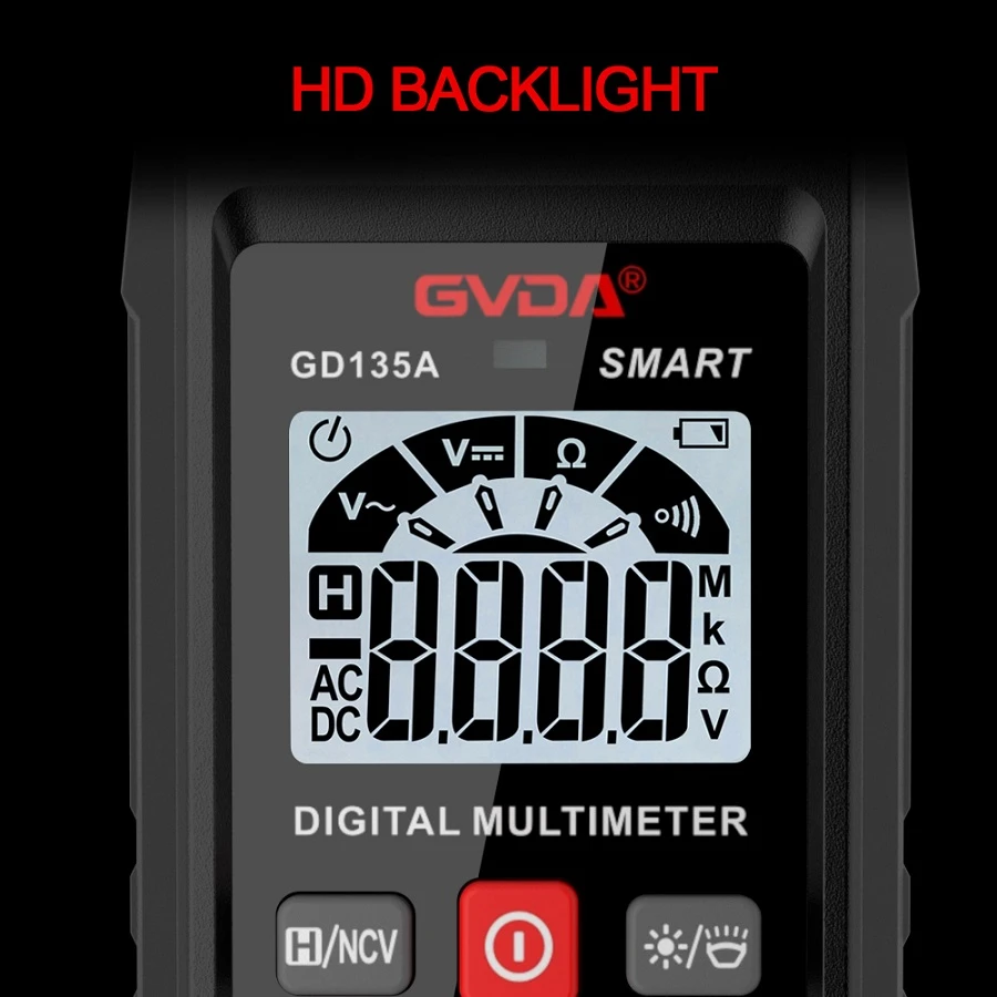
Emergency In-circuit Resistance Testing by Digital Multimeter
(1) The full-scale test voltage and open-circuit voltage of the resistance range vary among different models of digital multimeters. Therefore, the value range of the loading resistor R₁ shall be determined experimentally.
(2) During operation, connect the loading resistor R₁ across the V/Ω and COM jacks of the digital multimeter first. Read the measured value of R₁ on this resistance range of the digital multimeter before carrying out in-circuit resistance measurement. Do not connect the circuit under test first and then parallel the resistor R₁. The relatively high test voltage of the multimeter resistance range may turn on silicon transistors in the circuit under test, rendering the measurement meaningless and causing large measuring errors. This operation sequence must not be reversed.
(3) In common circuits, resistors parallel to the emitter junction and collector junction of transistors are mostly in the range of kΩ to several hundred kΩ, while resistors of tens of ohms are rare. Therefore, for in-circuit measurement, set the digital multimeter to a medium range first, i.e., the 200 kΩ range (resolution 0.1 kΩ) or the 20 kΩ range. If the measured value R=R1·RX/(R1+RX) equals zero or is very small, it indicates a short-circuit fault in the circuit under test (RX=0) or that the selected range is too high. Switch to a low range (2 kΩ range) for detailed measurement. If the measured value R=R1·RX/(R1+RX) is close to R₁, it suggests an open-circuit fault in the circuit under test (RX=∞) or that the selected range is too low. Re-measure with a higher range (2 MΩ range).
(4) The 200 Ω and 20 MΩ resistance ranges are seldom used for in-circuit measurement. Since the loading resistor R₁ is paralleled with the measured resistor RX, the measuring range of the resistance range is actually extended and the capability for high-resistance measurement improved. Thus the 2 MΩ range is generally sufficient. Besides, the 2 kΩ range has a resolution of 1 Ω, which is adequate for judging whether in-circuit transistors in the tested circuit have short-circuit breakdown. Normally, three loading resistors are enough to meet the requirements of in-circuit resistance measurement. Take the DT830A digital multimeter as an example: set R1=R0=1 kΩ for the 2 kΩ range, R1=0.47R0=47 kΩ for the 200 kΩ range, and R1=0.47R0=470 kΩ for the 2 MΩ range. A 470 kΩ potentiometer can also replace these three loading resistors.
(5) After finishing in-circuit resistance measurement, remember to remove the loading resistor R₁ connected across the V/Ω and COM jacks of the digital multimeter in a timely manner. Otherwise, normal use of the multimeter will be affected, and accidents may occur when measuring high voltage.