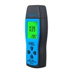
A digital multimeter (DMM) is a measuring instrument that uses the analog/digital conversion principle to convert the measured value into digital quantities and display the measurement results in digital form. Compared with pointer multimeters, digital multimeters are widely used because of their high precision, fast speed, large input impedance, digital display, accurate readings, strong anti-interference ability, and high degree of measurement automation. But if used improperly, it is easy to cause failure.
This article takes the digital multimeter as an example to talk about the general troubleshooting method of the digital multimeter.
Digital multimeter troubleshooting should generally start with the power supply. For example, after the power is turned on, if the liquid crystal cell displays, you should first check whether the voltage of the 9V stacked battery is too low; whether the battery leads are disconnected. Troubleshooting should follow the sequence of "inside first, first easy and then difficult". The troubleshooting of the digital multimeter can be roughly carried out as follows.
1. Visual inspection.
You can touch by hand whether the temperature rise of batteries, resistors, transistors, and integrated blocks is too high. If the newly installed battery is hot, the circuit may be shorted. In addition, the circuit should also be observed for disconnection, desoldering, mechanical damage, etc.
2. Detect working voltage at all levels.
Detect the working voltage of each point and compare it with the normal value. First, ensure the accuracy of the reference voltage. It is best to use a digital multimeter of the same model or similar to measure and compare.
3. Waveform analysis.
Use an electronic oscilloscope to observe the voltage waveform, amplitude, period (frequency), etc. of each key point of the circuit. For example, if the clock oscillator starts to oscillate and the oscillation frequency is 40kHz. If the oscillator has no output, it means that the internal inverter of the TSC7106 is damaged, or the external components may be open. Observe that the waveform of the {21} foot of TSC7106 should be a 50Hz square wave, otherwise, the internal 200 frequency divider may be damaged.
4. Measure element parameters.
For components within the fault range, perform on-line or off-line measurements, and analyze the parameter values. For on-line resistance measurement, the influence of components connected in parallel with it should be considered.
5. Hidden troubleshooting.
Recessive faults refer to the faults that appear and disappear from time to time, and the faults of the instrument are good and bad. This kind of fault is more complicated, and the common reasons include solder joints, loose, loose connectors, poor contact of the transfer switch, unstable component performance, and the lead will be broken continuously. In addition, it also includes some external factors. For example, the ambient temperature is too high, the humidity is too high, or there are intermittent strong interference signals nearby, etc.


