How to Check Whether an Inverter is Functional Using a Multimeter
① As we all know, inverters are equipped with multiple protection functions, such as overcurrent, overvoltage and overload protection. With the continuous improvement of industrial automation, inverters have been widely applied.
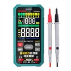
② During electronic circuit design, engineers inevitably use multimeters for measurement tasks. It is common knowledge that multimeters can measure DC current, AC voltage and DC voltage. An inverter is equipment that controls an AC motor by adjusting the frequency of its operating power supply. This article explains how to test whether an inverter is functional with a multimeter.
③ Important note: For personal safety, ensure the equipment is powered off. Disconnect the inverter input power lines R, S, T and output lines U, V, W before operation! Set the multimeter to the diode range, then perform the following tests with red and black test leads:
④ Connect the black test lead to the negative terminal P(+) of the DC bus. Touch the red test lead to R, S and T in sequence and record the readings. Next, connect the red test lead to N(−) and touch the black test lead to R, S and T in sequence and record the readings. If the six readings are roughly balanced, the rectifier diodes and soft-start resistors of the inverter are intact. Otherwise, the corresponding rectifier module or soft-start resistor is damaged, which may result in no display.
⑤ Connect the red test lead to the negative terminal P(+) of the DC bus. Touch the black test lead to U, V and W in sequence and record the readings. Then connect the black test lead to N(−) and touch the red test lead to U, V and W in sequence and record the readings. If the six readings are roughly balanced, the IGBT inverter modules of the inverter work normally. Otherwise, the corresponding IGBT module is damaged, causing no output or fault alarms.
⑥ On site, use the inverter to drive a power-matched asynchronous motor under no-load condition. Adjust frequency f downwards from 50 Hz to the minimum frequency.
⑦ Measure the no-load current of the motor with an ammeter during this process. If the no-load current remains stable and nearly constant as the frequency decreases, the inverter is in good condition.
⑧ The minimum frequency can be calculated by the formula: (Synchronous Speed − Rated Speed) × Number of Pole Pairs p ÷ 60. Example: For a 4-pole motor with rated speed of 1470 rpm, Minimum Frequency = (1500 − 1470) × 2 ÷ 60 = 1 Hz.