How to measure the quality of automotive sensors with a multimeter
1. The measurement method of the crankshaft position sensor depends on the circuit diagram to determine whether it is active or passive. There are two types of sensors in China, one is a Hall sensor and the other is an electromagnetic sensor. . The Hall sensor has 3 wires, which are 5V power supply, signal, and ground. The measurement method is to measure the signal with the red test lead of the DC voltage gear of the multimeter, and the black test lead is directly connected to the negative pole! Here I want to tell you how to measure the signal. The sensor is on the car, do not disassemble it, and do not pull out the plug. Use a thin steel wire to measure the back of the plug!
After connecting the wires, turn the crankshaft pulley with a wrench and turn it slowly. If the crankshaft position sensor is good, you will find that the voltage of the multimeter will display 0 degrees for a while and 5 volts for a while. Do not turn it too fast. Fault if not. The second is the magnetoelectric crankshaft position sensor. Its measurement method is relatively simple. Pull out the plug directly. There are 2 pins inside. Use a multimeter with AC voltage gear, and the red and black test leads are connected to these two pins. Then connect the wires, start the engine, there is no voltage when the engine crankshaft does not rotate, start the engine, you can see a voltage of more than ten volts, it may be higher, which means it is good.
2. The camshaft position sensor is Hall’s. The measurement method of the Hall’s crankshaft sensor is the same as that of the Hall’s crankshaft sensor above. It is also connected to the wire. I slowly turn the crankshaft with a wrench to see if there is any voltage change. This requires turning on the ignition switch.
3 intake air temperature sensor, the intake air temperature sensor is now integrated in the air flow meter, or the manifold pressure sensor.
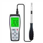
Air flow meter
Its measurement method is also relatively simple. First look for the circuit diagram to find out which two are the pins of the intake air temperature sensor. The intake air temperature sensor is generally a resistor, which changes with temperature. Use a multimeter with resistance gears, black and red Connect the test leads to the two pins found out. This sensor needs to be heated with a hair dryer. See if the size of the resistance changes, if it does not change, it will fail.
3 The measurement method of the manifold pressure sensor also needs to look for the circuit diagram to see which one is powered by 5 volts, which one is the signal, and which one is the ground iron. The side measurement method is to remove the intake air pressure sensor from the intake manifold. Turn on, use a thin steel wire to connect the back to lead out the signal, use a multimeter with a DC voltage file, connect the red test lead to the signal, and connect the black test lead to the iron, preferably the negative pole of the battery! Use a vacuum to connect to the interface of the intake pressure sensor to draw a vacuum. It can be seen that the voltage is changing, and it does not become a fault. There are more and more sensors on the car. If you want to be able to measure, you must first understand what signal it outputs, whether it is changing voltage or changing resistance. Also waveform signal.