How to measure Zener diodes with a needle multimeter
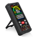
How to measure Zener diode with pointer multimeter
The voltage stabilization value of the voltage regulator tube is generally greater than 1.5V, and the resistance range below R×1k of the pointer meter is powered by the 1.5V battery in the meter. In this way, it is convenient to use the resistance range below R×1k to measure the voltage regulator tube. Just like a measuring diode, it has complete one-way conductivity. However, the R×10k range of the pointer meter is powered by a 9V or 15V battery. When using R×10k to measure a voltage regulator tube with a voltage regulator value less than 9V or 15V, the reverse resistance will not be ∞, but will have a certain value. resistance, but this resistance is still much higher than the forward resistance of the voltage regulator tube. In this way, we can initially estimate the quality of the voltage regulator tube.
However, a good voltage regulator tube must have an accurate voltage regulator value. How to estimate this voltage regulator value under amateur conditions? It's not difficult, just find an analog watch. The method is: first put a meter in the R×10k position, and connect its black and red test leads to the cathode and anode of the voltage regulator tube respectively. At this time, the actual working state of the voltage regulator tube is simulated, and then take another meter and put it in the R×10k position. At the voltage level V×10V or V×50V (according to the voltage regulator value), connect the red and black test leads to the black and red test leads of the watch just now. The voltage value measured at this time is basically this The voltage stabilization value of the voltage regulator tube.
I say "basically" because the bias current of the voltage regulator tube of the first meter is slightly smaller than the bias current during normal use, so the measured voltage regulator value will be slightly larger, but the difference is basically not big. . This method can only estimate the voltage regulator tube whose voltage regulator value is less than the voltage of the high-voltage battery of the pointer meter. If the voltage stabilization value of the voltage regulator tube is too high, it can only be measured with an external power supply (from this point of view, when we choose a pointer meter, it is more suitable to use a high-voltage battery with a voltage of 15V than a 9V one).
The semiconductor diode testing method is shown in Figure 1. The multimeter is set to R×100 or R×1k block. Connect the negative test lead (battery + terminal) of the multimeter to the "+" terminal of the diode; connect the positive test lead to the "-" terminal of the diode, that is, apply a forward voltage to the diode, the diode is in a conductive state, and the meter reads its forward resistance value. . If the silicon diode is being measured and the meter pointer points to the middle of the surface or a little to the right of the middle, it indicates that the forward characteristics are good. Then switch the positive and negative test leads. The positive test lead is connected to the "+" end of the diode, and the negative test lead is connected to the "-" end of the diode. At this time, the diode adds a reverse voltage and is in a cut-off state. For silicon tubes, the hands of the meter almost move. That is, the resistance value is about ∞; if the germanium diode is measured, the resistance values of the two characteristics are both too small. The results of the two tests are as mentioned above, indicating that the tube has unidirectional conductive properties, indicating that the tube under test is intact. Otherwise it means it is a bad pipe.
To determine the polarity of a diode, first determine whether it is good or bad through the above two tests. As long as the tube is intact, if the measured result is a small resistance, it means that the measured resistance is forward resistance, and the end of the multimeter's negative test lead is the "+" terminal of the diode (remember that the negative test lead of the multimeter is the + terminal of the battery E in the meter) ); if the measured resistance value is large, the negative test lead is connected to the "-" pole of the diode.