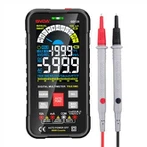
Practical Troubleshooting & Repair Techniques for Digital Multimeters
① Turn the meter‑under‑test to its lowest DC‑voltage range.
② Measure whether the operating voltage of the A/D converter is normal. According to the model of the built‑in A/D converter, measure the voltage between pin V+ and pin COM, and compare the measured value with its typical value for consistency.
③ Measure the reference voltage of the A/D converter. Most common digital multimeters adopt a reference voltage of 100 mV or 1 V. Measure the DC voltage between REF+ and COM. If the reading deviates from 100 mV or 1 V, adjust it by means of an external potentiometer.
④ Check the display reading at zero input. Short‑circuit the positive input terminal IN+ and negative input terminal IN‑ of the A/D converter so that input voltage Vin = 0. The meter shall display "00.0" or "00.00".
⑤ Check all illuminated segments of the display. Short‑circuit the TEST pin and positive‑supply pin V+. This pulls the logic ground to a high potential and halts all digital‑circuit operations. DC voltage is applied to every segment, so all segments light up; a 3½‑digit meter shows "1888" and a 4½‑digit meter shows "18888". If any segment is missing, inspect for poor contact or broken connections between the corresponding output pins of the A/D converter, conductive rubber (or connecting wires), and the display.
⑥ If only individual ranges malfunction, the A/D converter and power‑supply section are working properly. The DC‑voltage and resistance ranges share the same voltage‑divider resistors; AC‑ and DC‑current ranges share the shunt assembly; AC‑voltage and AC‑current ranges share one AC/DC converter. Other functions such as Cx, HFE and frequency F use separate, independent converters. Once you understand these correlations and refer to the schematic diagram, fault locations can be readily identified. For inaccurate small‑signal measurements or severe digit‑flickering, prioritize checking whether the range selector switch makes good contact.