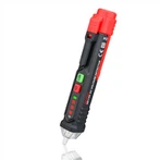
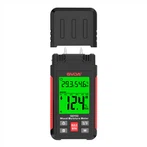
Precautions for Testing Engine Electronic Control System with a Multimeter
(1) Unless otherwise specified during the testing process, a pointer type multimeter cannot be used to test computers and sensors. A high impedance digital multimeter should be used, and the internal resistance of the multimeter should not be less than 1OK Ω.
(2) Firstly, check the condition of the fuses, fusible wires, and wiring terminals. After troubleshooting these areas, use a multimeter for inspection.
(3) When measuring voltage, the ignition switch should be turned on, and the battery voltage should not be lower than 11V.
(4) When checking waterproof connectors with a multimeter, be careful to remove the leather sleeve and insert the test probe into the connector to check. Do not apply too much force to the terminals. During testing, the test probe can be inserted from the back end with wiring or from the front end without wiring.
(5) When measuring resistance, gently shake the wire in both vertical and horizontal directions to improve accuracy.
(6) When checking for open circuit faults in the circuit, the connectors of the computer and corresponding sensors should be disconnected first, and then the resistance between the corresponding terminals of the connector should be measured to determine whether there is an open circuit or contact fault.
(7) When checking for a short circuit to ground in a circuit, the connectors at both ends of the circuit should be disconnected, and the resistance value between the tested terminal of the connector and the vehicle body (ground) should be measured. A resistance value greater than 1M Ω indicates no fault.
(8) Before disassembling the engine electronic control system wiring, the power should be cut off first, that is, the ignition switch should be turned off (OFF), and the wiring on the battery pole should be removed.
(9) The symbol of the grounding terminal on the connector varies depending on the vehicle model, and attention should be paid to identifying it according to the maintenance manual.
(10) When measuring the voltage between two terminals or between two lines, the two probes of the multimeter (voltage range) should be in contact with the two terminals or wires being measured.
(11) When measuring the voltage of a certain terminal or line, the positive probe of the multimeter should be in contact with the tested terminal or line; And contact the negative probe of the multimeter with the ground wire.
(12) Checking the continuity of terminals, contacts, or wires refers to checking whether the terminals, contacts, or wires are energized but not disconnected. The resistance value can be measured using a multimeter resistance range to check.
(13) When measuring resistance or voltage, the connector is usually disassembled, which divides the connector into two parts, one of which is called a sensor (or actuator) connector; The other part is called a sensor (or actuator) wire harness connector or a sensor (or actuator) connector (or connector sleeve) on one side of the wire harness. For example, after removing the connector on the fuel injector, one part is called the fuel injector connector, and the other part is called the fuel injector wiring harness connector or the fuel injector connector on one side of the wire. When measuring, it is important to determine which part of the connector it is.
(14) All sensors, relays, and other devices are connected to computers, which are connected through wires and actuators. Therefore, when checking for faults, testing can be conducted on the corresponding terminals of computer connectors.