Structure and principle of the clamp-on meter
Structure of Clamp Meter
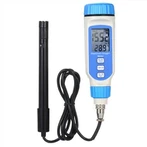
Clamp meter is mainly composed of clamp head, clamp head trigger, hold switch, rotary switch, LCD display, pen jack and red and black pens and other parts.
1, the clamp head of the clamp meter is mainly used for measuring AC current clamp the measured wire, the use of current transformer principle of sensing wire current.
2, clamp meter clamp trigger is mainly used to open and close the clamp head, press the clamp head open, release the clamp head closed.
3, the clamp meter to keep the switch is mainly used to detect electronic circuits to keep the measured data, in order to facilitate the reading of recorded data.
4, the rotary switch of the clamp meter is mainly for the characteristics of the clamp meter, set the corresponding range for different tests.
5, the clamp meter LCD display is mainly used to display test data, data units, select the range and other information.
6, the meter pen jack is mainly used to connect the meter pen lead plug and insulation test accessories. The red pen is connected to the VΩ jack, and the black pen is connected to the ground terminal.
Principle of Clamp Meter
Clamp ammeter is a combination of current transformer and ammeter. The core of the current transformer in the pinch spanner can be open, the measured current through the wire can not be cut off through the core of the open gap, when the release of the wrench core closed, through the core of the measured wire becomes the primary coil of the current transformer, which passes through the current will be induced in the secondary coil of the current. Thus, the ammeter connected to the secondary coil indicates the current of the line under test.