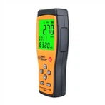
Test items of digital multimeter
1. Voltage measurement
One of the most basic functions of a digital multimeter is to measure voltage. Testing voltages is usually the first step in troubleshooting a circuit. If there is no voltage or the voltage is too low or too high, first fix the power source before checking further.
The waveform of the AC voltage may be sinusoidal (sine wave) or non-sinusoidal (sawtooth, square, etc.). Many DMMs can display "rms" (effective value) of AC voltage. The effective value is the value at which the AC voltage is equivalent to the DC voltage.
Many meters have an "average responding" function that gives an effective value when fed a pure sine wave. This meter cannot accurately measure the effective value of non-sinusoidal waves. A digital multimeter with a true-rms function (true-rms) can accurately measure the true-rms value of a non-sine wave.
The ability of a DMM to measure AC voltage is limited by the frequency of the signal being measured. Most DMMs can accurately measure AC voltages from 50 Hz to 500 Hz. However, the AC measurement bandwidth of the digital multimeter can reach hundreds of kilohertz. For AC voltage and current, the frequency range should be consistent with the digital multimeter specifications.
1. Measurement of DC voltage
①Insert the black test lead into the COM jack, and the red test lead into the V/Ω jack.
②Set the function switch to the DC voltage range V-range, and connect the test lead to the power supply (to measure the open circuit voltage) or the load (to measure the load voltage drop), and the polarity of the terminal connected to the red test lead will be displayed on the display at the same time superior.
③ Check the reading and confirm the unit
Note:
① If you do not know the voltage range to be measured, set the function switch to the maximum range and gradually decrease it.
②If the display only shows "1", it means over-range, and the function switch should be set to a higher range.
③ "" means do not measure the voltage higher than 1000V, it is possible to display a higher voltage value, but there is a danger of damaging the internal circuit.
④ When measuring high voltage, pay special attention to avoid electric shock.
2. Measurement of AC voltage
①Insert the black test lead into the COM jack, and the red test lead into the V/Ω jack.
②Put the function switch in the range of AC voltage range V~, and connect the test pen to the power supply or load to be tested. The test connection diagram is the same as above. When measuring AC voltage, there is no polarity display.
2. Current measurement
1. Measurement of DC current
①Insert the black test lead into the COM jack. When measuring the maximum current of 200mA, insert the red test lead into the mA jack. When measuring the maximum current of 20A, insert the red test lead into the 20A jack.
②Put the function switch in the DC current range A-range, and connect the test leads in series to the load to be tested. While the current value is displayed, the polarity of the red test leads will be displayed.
Notice:
1. If you do not know the measured current range before use, set the function switch to the maximum range and gradually decrease it.
2. It means that the maximum input current is 200mA. Excessive current will burn out the fuse, which should be replaced again. The 20A range has no fuse protection, and the measurement should not exceed 15 seconds.
2. Measurement of AC current
The measurement method is the same as 1, but the gear should be set to the AC gear. After the current measurement is completed, the red pen should be inserted back into the "VΩ" hole. If you forget this step and directly measure the voltage, the meter or power supply will be scrapped!
3. Resistance measurement
Insert the test leads into the "COM" and "VΩ" holes, turn the knob to the required range in "Ω", and connect the test leads to the metal parts at both ends of the resistor.
Notice:
1. If the measured resistance value exceeds the maximum value of the selected range, it will display over-range "1", and a higher range should be selected. For a resistance greater than 1MΩ or higher, it will take a few seconds for the reading to be stable. This is normal.
2. When there is no connection, such as an open circuit, the meter will display "1".
3. When checking the impedance of the line under test, ensure that all power sources in the line under test are removed and all capacitors are discharged. If there are power sources and energy storage components in the line under test, it will affect the accuracy of the line impedance test.
4. For the 200MΩ range of the multimeter, there are 10 digits when there is a short circuit. When measuring a resistance, these 10 digits should be subtracted from the measurement reading. For example, when measuring a resistance, it is displayed as 101.0, and 10 characters should be subtracted from 101.0. The actual resistance value of the measured component is 100.0, which is 100MΩ.
5. You can touch the resistance with your hands during the measurement, but do not touch both ends of the resistance with your hands at the same time - the human body is a conductor with high resistance but finite size.
4. Diode measurement
The digital multimeter can measure light-emitting diodes, rectifier diodes... When measuring, the position of the test leads is the same as that of the voltage measurement, turn the knob to the " " position; connect the red test lead to the positive pole of the diode, and the black test lead to the negative pole, and the positive direction of the diode will be displayed at this time. pressure drop. The voltage drop of the Schottky diode is about 0.2V, that of ordinary silicon rectifiers (1N4000, 1N5400 series, etc.) is about 0.7V, and that of light-emitting diodes is about 1.8-2.3V. Replace the test leads, if the display shows "1.", it is normal, because the reverse resistance of the diode is very large, otherwise the tube has been broken down.
5. Measurement of triode
The insertion of the test leads is the same as above; the principle is the same as that of a diode. First assume that pin A is the base, connect the pin with a black pen, and touch the other two pins with the red pen; if the two readings are about 0.7V, then connect the pin with a red pen, black pen Touch the other two pins, if both display "1", then the A pin is the base, otherwise it needs to be re-measured, and this tube is a PNP tube. So how to judge the collector and emitter? The digital meter cannot be judged by the swing of the pointer like the pointer meter, so what should we do? We can use the "hFE" gear to judge: firstly switch the gear to the "hFE" gear, and you can see that there is a row of small jacks next to the gear, which are divided into PNP and NPN tube measurements. The tube type has been judged before, insert the base into the "b" hole of the corresponding tube type, and insert the other two legs into the "c" and "e" holes respectively. At this time, the value can be read, that is
β value; fix the base again, and swap the other two pins; compare the two readings, and the position of the pin with the larger reading corresponds to the "c" and "e" on the surface.
Tip: The above method can only directly measure small tubes such as 9000 series. If you want to measure large tubes, you can use the wiring method, that is, use small wires to lead out the three pins. This is much more convenient.
6. Measurement of MOS field effect tube
N-channel products include domestically produced 3D01, 4D01, and Nissan's 3SK series. Determination of G pole (gate): use the diode file of the multimeter. If the positive and negative voltage drops between one pin and the other two pins are greater than 2V, it will display "1", and this pin is grid G. Then exchange the test leads to measure the other two feet. In the case of the small voltage drop, the black test lead is connected to the D pole (drain), and the red test lead is connected to the S pole (source).
1. Voltage file:
When testing or manufacturing, it can be used to measure the voltage of each pin of the device, and compare it with the normal voltage to find out whether it is damaged. It can also be used to detect the voltage regulation value of the Zener diode with a small voltage regulation value. The principle is shown in the figure: R is 1K, and the voltage at the power supply terminal depends on the nominal voltage regulation value of the Zener diode, which is generally larger than the nominal voltage. More than 3V, but not more than 15V. Then use a multimeter to detect the voltage value at both ends of tube D, which is the actual regulated voltage value of tube D.
2. Current gear
Connect the meter in series to the circuit to measure and monitor the current. If the current deviates far from the normal value (based on experience or the original normal parameters), the circuit can be adjusted or repaired if necessary. You can also use the 20A range of the meter to measure the short-circuit current of the battery, that is, connect the two test leads directly to the two ends of the battery. Remember that the time must not exceed 1 second! Note: This method is only suitable for dry batteries, AAA and AAA rechargeable batteries, and beginners must be under the guidance of personnel familiar with maintenance, and must not operate by themselves! The performance of the battery can be judged according to the short-circuit current. In the case of a fully charged battery of the same type, the larger the short-circuit current, the better.
3. Resistance file;
One of the methods that can be used to judge the quality of resistors, diodes, and triodes. When the actual resistance value of the resistor deviates too much from the nominal value, it is damaged. For the two-transistor, if the resistance between any two pins is not very large (above hundreds of K), it can be considered that the performance has declined or has been damaged by breakdown. Note that this triode is not blocked. This method can also be used for integrated blocks. It should be noted that: the measurement of integrated blocks can only be compared with the normal parameters.
4. The test leads of ordinary multimeters have a large resistance value. Interested enthusiasts can make a pair of test leads by themselves; method: prepare high-quality speaker wires or multi-core copper wires of about one meter, and a pair of clips with insulating sleeves (red Black), a pair of banana plugs (red and black) for speaker wiring; one end of the line is welded firmly on the clip, and the other end is connected to the banana plug; a pair of good test leads is done.
7. Capacitance test
Before connecting the capacitor to be tested, please note that it takes time to reset each time the range is changed, and the existence of drift readings will not affect the test accuracy.
⒈Set the function switch to the capacitance range C (F)
2. Insert the capacitor into the capacitance test socket
Notice:
⒈The instrument itself has set the protection for the capacitance file, so there is no need to consider the polarity and the charging and discharging of the capacitance during the capacitance test.
2. When measuring capacitance, insert the capacitance into the dedicated capacitance test socket.
3. It takes a certain amount of time to stabilize the reading when measuring large capacitance.
4. Capacitance unit conversion: 1μF=106pFlμF=103nF
8. Continuity test
1. Insert the black test lead into the COM jack, and the red test lead into the V/Ω jack (the polarity of the red test lead is "+"). Set the function switch to the "what" position, and connect the test lead to the diode to be tested, and the reading is the positive value of the diode. Approximate value for pressure drop.
2. Connect the test leads to the two ends of the line to be tested. If the resistance between the two ends is lower than about 70Ω, the built-in buzzer will sound.