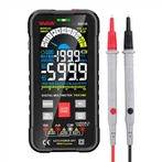
Multimeter maintenance skills introduction
1. Repair technique You should start searching for problems on the outside before moving inside. The following categories can be used to generally group the methods:
The sensory approach uses the senses to evaluate the root of the problem directly. Visual inspection can reveal issues like disconnecting, desoldering, short circuits, burnt components, broken fuse tubes, mechanical damage, copper foil on the printed circuit, and fractures, among others; you can also feel the battery, resistors, transistors, and integrated circuits' temperature rise and look at the circuit diagram to determine what's causing the abnormal temperature rise. Additionally, you can visually inspect the transfer switch, the integrated circuit pins, and the components by hand. You can also use your senses of hearing and smell to detect any unusual sounds or scents.
voltage gauge technique determines whether the working voltage at each important location is normal and is capable of locating the fault point fast. such as checking the A/D converter's functioning voltage and reference voltage.
a shortcut technique The A/D converter inspection method discussed above often employs the short-circuit method, which is frequently employed in the repair of fragile and microscopic electric devices.
open-circuit technique Remove the suspect component from the circuit of the entire machine or unit. If the fault goes away, the severed circuit is where it is located. The majority of the time, this approach works well when the circuit has a short circuit.
Method for locating elements The issue can be measured online or offline after it has been narrowed down to a specific area or many components. Replace it, if necessary, with a suitable one. If the issue goes away, the component is damaged. 6. Using interference Utilize the interference signal produced by the human body's induced voltage to track changes in the liquid crystal display, which is frequently done to ensure that the input circuit and display component are both sound.
2. Repair expertise In the case of a malfunctioning instrument, you should first determine if the fault phenomena is widespread (all functions cannot be measured) or specific (particular functions or individual ranges), after which you should make a diagnosis and deal with the problem symptomatically.
Focus on testing the power circuit and A/D converter circuit if none of the gears function. Take off the laminated battery, turn on the power, connect the positive test lead to the negative of the power supply of the meter being tested and the negative test lead to the positive power supply (for digital multimeters), then switch to the diode measurement position to see if it indicates the power supply part is functioning properly. A good power supply component indicates a higher forward voltage of the diode. A high variation indicates a problem with the power supply component.Concentrate on inspecting the power switch and battery leads if there is an open circuit. To verify the operational amplifier, timer, and A/D converter if there is a short circuit, progressively detach the parts that depend on the power source using the open circuit approach. Usually, more than one integrated component is harmed in a short circuit. The analog multimeter's basic meter head, which is comparable to the DC meter head, can be used to simultaneously test the A/D converter.
Specific inspection procedure: (1) The meter being tested is set to its lowest DC voltage setting;
(2) Check to see if the A/D converter's working voltage is normal. Check to determine if the observed value is consistent by comparing it to its normal value using the A/D converter model that corresponds to the V+ pin and COM pin in the table.
(3) Check the A/D converter's reference voltage. Measure the DC voltage between VREF+ and COM using a typical digital multimeter with a reference voltage of 100 mV or 1 volt. You can utilize the external potentiometer if it deviates from 100mV or 1V. Make modifications.
(4) Verify the displayed value when the input is zero and the meter reads "00.0 or "00.00. To do this, short-circuit the positive terminal IN+ and the negative terminal IN- of the A/D converter to create the input voltage Vin=0.
(5) Inspect the display's full range of brightness. All digital circuits become unresponsive when the test terminal TEST pin and the positive power supply terminal V+ are connected in series. All strokes are bright and the alignment table displays "1888" as a result of the addition of DC voltage to each stroke. If there aren't any strokes, see if the conductive glue (or wiring), the matching output pin of the A/D converter, and the display have poor contact or are disconnected.