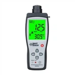
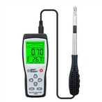
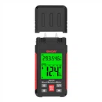
The multimeter's resistance setting does not display the value when measuring the forward and reverse resistance of the diode.
Why can't diodes be measured using a resistance scale?
The unidirectional conduction characteristics of the diode are conditional, that is, the PN junction of the diode must be forward biased before it conducts. If you simply use the resistance setting to measure the resistance, the diode itself will not conduct, so the resistance cannot be measured. The diode settings of the multimeter are all charged, usually about 1.5-2.8V. When measuring the diode, the voltage is actually added to both ends of the diode to forward bias the PN junction. Only then do I see about 0.7V on the multimeter. The voltage drop proves that the diode is good. The resistance of about 10K measured by the pointer meter is not accurate, and the values obtained by measuring different diodes are also different.
How to measure diodes with a multimeter
You must use the diode scale of a multimeter to measure the diode. Turn the multimeter to the diode setting, insert the red test lead into the positive terminal, and insert the black test lead into the negative terminal.
Use the red test lead and the black test lead to touch the two electrodes of the diode under test. If the diode shows a voltage drop of about 0.7V, it means that one end of the red test lead is the anode of the diode, and the other end is the cathode of the diode.
Replace the direction of the diode under test. If no voltage value is measured, it means that the red test lead is in contact with the cathode of the diode and the black test lead is in contact with the anode of the diode.
After the above two measurements, the positive and negative poles of the diode can be confirmed, and the quality of the diode can be confirmed.
When the digital multimeter is in the resistance mode, the voltage between the two test leads is low, lower than the forward conduction voltage of about 0.6-0.7V of ordinary silicon diodes, and the diodes are in a cut-off state. The resistance value in the cut-off state is very large, so when measuring the diode with a digital multimeter, whether it is forward or reverse, the display value will overflow. The digital multimeter has a diode measurement range, which should be used to measure the forward and reverse continuity of the diode.
In addition, the diode is a non-linear component, and the resistance value is not fixed. When the forward conduction resistance of the diode is measured with the resistance range of a pointer multimeter, it can be seen that the resistance value of different settings is very different. Therefore, it is of little significance to use a multimeter to measure the resistance value of the diode. As long as it can measure the forward conduction and reverse cutoff, or identify the positive and negative poles, and determine whether there is breakdown or burnout, there is no need to read the specific resistance value. resistance.
The digital multimeter has a special diode measurement setting for testing diodes. If you have to use the resistance scale to measure, the diode has a resistance value of more than tens of K in the reverse direction, so the meter will overflow 1. There are several hundred ohms to several K in the forward direction. Because the voltage applied to both ends of the semiconductor diode is different, the resistance value is different. Therefore, when measuring diodes, a special setting is generally used. The reverse value is generally 1 (overflow), and the forward value is between 300 and 750 (this is actually the voltage drop). Most of them are around 600 (silicon) and below 500 (germanium) tubes. .