The working principle of the multimeter and the function of the panel knob
(1) LCD display screen: The display digit of a multimeter is 4, and because the highest digit (thousand digit) can only display the number "1" or not, it is counted as half digit, collectively referred to as half digit
The working principle of a multimeter and the function of the panel knob
Position (pronounced as three and a half). The maximum display count is 1999 or -1999. When measuring DC voltage and DC current, the instrument has an automatic polarity display function. If the measured value is negative, the displayed number will be preceded by a "-" sign. When the instrument input is overloaded, "1" or "-1" appears on the screen.
(2) Range switch: The rotary range switch is located in the center of the panel and is used to convert the type and range of work. Use different colors and boundary lines to mark the range of various working states around the switch.
(3) Input socket: The input socket is the part where the multimeter is connected to the measuring point through the probe, and has four holes: "COM", "V. Ω", "mA", and "10A". The negative probe should always be placed in the "COM" socket, and the positive probe should be placed in "V. Ω", "mA" or "10A" according to the type of work and the size of the measured value. On the connection between "COM" and "V. Ω", there are markings indicating that when input from these two holes, the measured AC voltage should not exceed 750V and the measured DC voltage should not exceed 1000V. At this point, the measurement of "V" and "Ω" are both in the same socket, so it is important to carefully check whether the range switch selection position is correct. There are also markings on the wires between "COM" and "mA" and between "COM" and "10A", indicating that the measured current value between the corresponding sockets cannot exceed 200mA and 10A.
(4) HFE socket: This socket is used to insert the transistor under test. When measuring, the e, b, and c pins of the tube should be inserted into the three holes of "E", "B", and "C" respectively. "E" has two holes with the same function, and the emitter pin can be easily inserted.
(5) Power switch: When the switch is placed in the "ON" position, the power supply in the meter is connected and can work normally. When the switch is placed in the "OFF" position, the power is turned off.
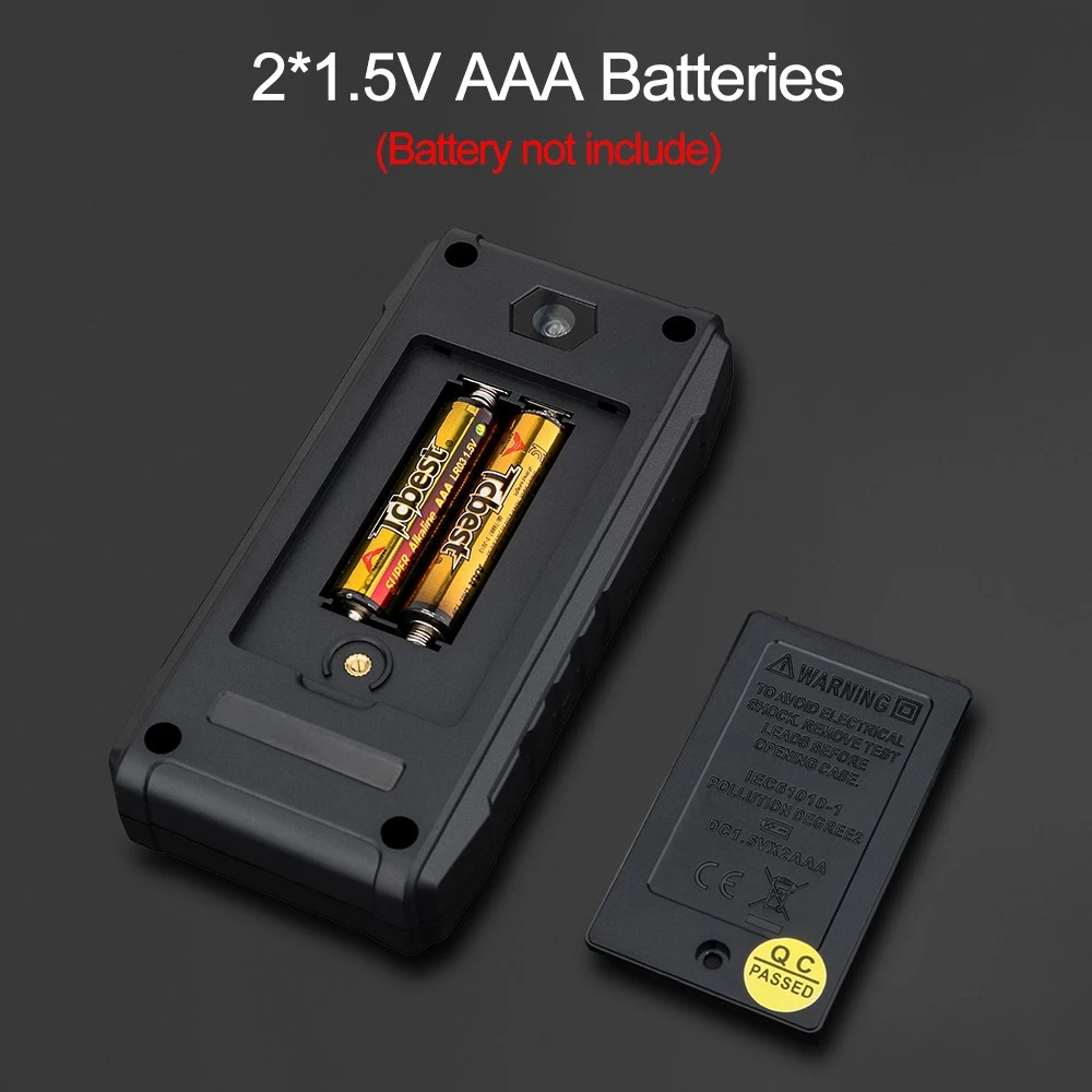
The DT-830 multimeter uses a 9V small battery and is installed in the battery box inside the meter. There is also a 0.5A quick fuse inside the battery box. When the "DC. A" and "AC. A" ranges are overloaded for measurement, the fuse will be immediately blown to provide protection, and there will be no reading on the display at this time.