
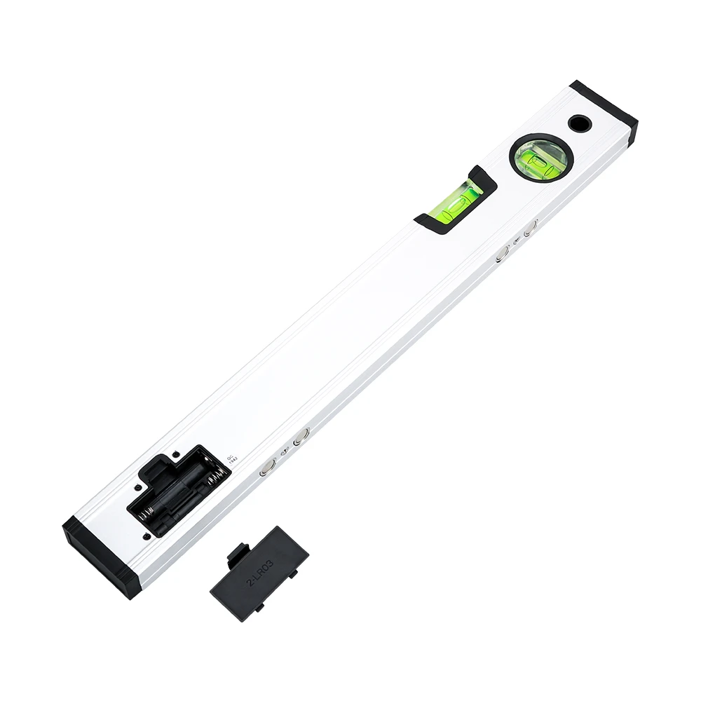
The use and reading of a level gauge
A level gauge is an instrument used to check the unevenness of various machine tools and other mechanical equipment guides, the parallelism of relative positions of machine parts, and the horizontal and vertical positions of equipment installation. A level gauge is a basic inspection tool in the manufacturing, installation, and repair of machine tools. The overall size of a general frame level is 200 × 200mm, with an accuracy of 0.02/1000. The scale value of a level is the inclination of a bubble when it moves one grid, measured in seconds or millimeters per meter. The scale value is also known as reading accuracy or sensitivity. If the level is placed on a surface of a 1-meter long ruler, with a height of 0.02mm at the right end, and the ruler is tilted for 4 seconds, the movement distance of the bubbles will be exactly one scale. As shown in the figure: 1
The calculation is as follows: the inclination angle of the level and the ruler α The size of can be determined from the following equation:
By tg α=== 0.00002 α= 4 seconds
From the above equation, it can be seen that the bubble of a 0.02/1000 precision frame level moves one scale and its tilt angle is equal to 4 seconds. At this point, at a distance of 200mm from the left end (equivalent to one side length of the level), calculate the height H1 below the level as:
Tg α= = 0.00002 H1=tg α× L1=0.0002 × 200=0.004 (mm)
From the above equation, it can be seen that the actual change value of the level gauge bubble is related to the length of the level gauge pad used. If the level gauge is placed on a 500mm long pad iron to measure the machine tool guide rail, then every movement of the bubble on the level gauge indicates that the height difference between the two ends of the pad iron is 0.01mm. In addition, the actual change value of the level is also related to the reading accuracy. So, when using a level gauge, it is important to pay attention to the length of the pad iron, reading accuracy, and the true value represented by the bubble movement when used alone.
From this, it can be concluded that the value of the bubble movement on the level after one grid is determined by the length of the pad iron.
The reading of the level gauge should be zero in any grid of its starting point. The count of bubbles moving one grid is 1, and the count of bubbles moving another grid is 2, which is used for accumulation. In actual production, whether grinding, precision grinding, or manual scraping are used for the final processing of the guide rail, most of the guide rails are in a simple convex or simple concave state, and it is rare for the straightness of the machine tool guide rail to produce curves (the guide rail before processing may have curves). When measuring the guide rail, the bubbles of the level generally move in one direction, and the convexity and concavity of the machine tool guide rail are determined by the direction of movement of the level and the direction of movement of the bubbles.
The direction of movement of the level is opposite to the direction of movement of the bubble and is convex, represented by the symbol "+".
The direction of movement of the level is the same as the direction of movement of the bubble, which is concave and represented by the symbol "-".
If the guide rail is convex, the level gauge (pad iron) moves in either direction, and the bubbles of the level gauge move in the opposite direction.
If the guide rail is concave, the level gauge (pad iron) moves in either direction, and the bubbles of the level gauge move in the same direction.
After determining the concavity and convexity of the guide rail, the accurate straightness error accuracy of the guide rail can be obtained by calculating half of the sum of the length of the pad iron used and the number of bubble motion grids on the level gauge.


